White Paper
The VAST Data Platform
Introduction
Copy link to clipboard
What is the VAST Data Platform?
Copy link to clipboard
The Rise of the Deep Learning Data Platform
Copy link to clipboard
The Promise of AI-Enabled Discovery
Copy link to clipboard
The VAST Data Platform
Copy link to clipboard
How It Works
Copy link to clipboard
Architecting the VAST Data Platform
Copy link to clipboard
The Disaggregated Shared Everything Architecture
Copy link to clipboard
VAST Servers (CNodes)
Copy link to clipboard
Stateless Containers
Copy link to clipboard
HA Enclosures (DBoxes)
Copy link to clipboard
Storage Class Memory
Copy link to clipboard
Hyperscale Flash
Copy link to clipboard
Asymmetric Scaling
Copy link to clipboard
Asymmetric and Heterogeneous
Copy link to clipboard
Server Pooling
Copy link to clipboard
Networking in DASE
Copy link to clipboard
Connect via Switch
Copy link to clipboard
Connect via CNode
Copy link to clipboard
Leaf-Spine for Large Clusters
Copy link to clipboard
Scale-Out Beyond Shared-Nothing
Copy link to clipboard
The Advantages of a Stateless Design
Copy link to clipboard
The VAST DataStore
Copy link to clipboard
Designing the VAST DataStore
Copy link to clipboard
Defining the DataStore
Copy link to clipboard
A New Approach to Metadata
Copy link to clipboard
Inherently Persistent
Copy link to clipboard
Transactionally Consistent
Copy link to clipboard
V-Trees for Fast Access
Copy link to clipboard
Database Semantics
Copy link to clipboard
Transaction Tokens
Copy link to clipboard
Bottom-Up Updates
Copy link to clipboard
Element Locking
Copy link to clipboard
The Physical Chunk Management Layer
Copy link to clipboard
Data Flows in the VAST DataStore
Copy link to clipboard
Read
Copy link to clipboard
Write to SCM
Copy link to clipboard
Migrate to Flash
Copy link to clipboard
Write in Free Space Indirection
Copy link to clipboard
Challenges with Commodity Flash
Copy link to clipboard
Endurance Is Write Dependent
Copy link to clipboard
VAST Datastore Data Structures
Copy link to clipboard
Optimized for Hyperscale Flash
Copy link to clipboard
With Large Data Stripes, Drives Never Need to Garbage Collect
Copy link to clipboard
VAST Foresight
Copy link to clipboard
Retention-Aware Data Protection Stripes
Copy link to clipboard
Endurance Is Amortized
Copy link to clipboard
A Breakthrough Approach to Data Reduction
Copy link to clipboard
Beyond Deduplication and Compression
Copy link to clipboard
Similarity Reduction to the Rescue
Copy link to clipboard
Similarity Reduction
Copy link to clipboard
A Single Reduction Realm
Copy link to clipboard
Similarity Reduction in Practice
Copy link to clipboard
A Breakthrough Approach to Data Protection
Copy link to clipboard
Wide Stripes for Storage Efficiency
Copy link to clipboard
Quad Parity for Higher Resilience
Copy link to clipboard
VAST Data Locally Decodable Codes
Copy link to clipboard
How Locally Decodable Erasure Codes Work
Copy link to clipboard
Storage-Class Memory Eliminates the Need for Nerd Knobs
Copy link to clipboard
Intelligent, Data-Only Rebuilds
Copy link to clipboard
Declustered Parity
Copy link to clipboard
A Fail-in-Place Cluster
Copy link to clipboard
VAST Checksums
Copy link to clipboard
Rack Scale Resilience via Enclosure HA
Copy link to clipboard
Encryption at Rest
Copy link to clipboard
The Logical Element Store Layer–Building Elements from Data Chunks
Copy link to clipboard
Inherently Scalable Namespace
Copy link to clipboard
Discovering a New Element – The Table
Copy link to clipboard
Element Store Data Services
Copy link to clipboard
Low-Overhead Snapshots and Clones
Copy link to clipboard
Truly Independent Clones
Copy link to clipboard
Indestructible Storage Protects from Ransomware and More
Copy link to clipboard
Protection Policies Unite Snapshots and Replication
Copy link to clipboard
VAST Replication
Copy link to clipboard
Snap-to-Object
Copy link to clipboard
Asynchronous “Native” Replication
Copy link to clipboard
Asynchronous Replication
Copy link to clipboard
Simple, Powerful Policies
Copy link to clipboard
Minimizing Recovery Point Objective
Copy link to clipboard
Clone Snapshots Anywhere with Global Clones
Copy link to clipboard
The Access Layer
Copy link to clipboard
Providing Multiprotocol Access to the VAST DataStore
Copy link to clipboard
Multiprotocol ACLs
Copy link to clipboard
QoS Silences Noisy Neighbors
Copy link to clipboard
VAST NFS
Copy link to clipboard
Parallel File System Speed, NAS Simplicity
Copy link to clipboard
Accelerating NFS for the AI Era
Copy link to clipboard
NFS over RDMA (NFSoRDMA)
Copy link to clipboard
With VAST NFS Means Now for Speed
Copy link to clipboard
NFS Version 4
Copy link to clipboard
VAST SMB
Copy link to clipboard
File Services for Windows and Macintosh
Copy link to clipboard
SMB Server Resilience
Copy link to clipboard
DASE and SMB Failover
Copy link to clipboard
VAST S3
Copy link to clipboard
Object Storage for Modern Applications
Copy link to clipboard
NVMe-Over TCP Block Services for the 21st Century
Copy link to clipboard
Ecosystem Integrations
Copy link to clipboard
Kubernetes CSI
Copy link to clipboard
Manilla
Copy link to clipboard
GPU Direct Storage
Copy link to clipboard
Ecosystem Validations
Copy link to clipboard
More to Come
Copy link to clipboard
The VAST DataSpace
Copy link to clipboard
VAST Goes Global
Copy link to clipboard
Eventually Consistent Isn’t Consistent Enough
Copy link to clipboard
Write Leases Ensure Consistency
Copy link to clipboard
VAST Cloud Instances
Copy link to clipboard
Ephemeral Clones
Copy link to clipboard
Persistent Cloud Instances
Copy link to clipboard
Cloud Instances and Global Clones
Copy link to clipboard
DataSpace Command
Copy link to clipboard
Global Management
Copy link to clipboard
DataSpace Command for Cloud Control
Copy link to clipboard
The VAST DataBase
Copy link to clipboard
Storing Data in Rows or Columns
Copy link to clipboard
Improved Reducibility
Copy link to clipboard
VAST’s Columnar DataStore
Copy link to clipboard
Accessing the VAST DataBase
Copy link to clipboard
Database File Ingest
Copy link to clipboard
Both Analytical and Transactional
Copy link to clipboard
Merging Content and Context with the VAST Catalog
Copy link to clipboard
Enter The Catalog
Copy link to clipboard
Extensive and Extendable
Copy link to clipboard
Inseparable Context
Copy link to clipboard
Catalog Snapshots Add The Dimension of Time
Copy link to clipboard
The VAST DataEngine
Copy link to clipboard
Event Triggers and Functions
Copy link to clipboard
Event Triggers
Copy link to clipboard
Functions
Copy link to clipboard
The VAST Computing Environment
Copy link to clipboard
The Global Workflow Optimization Engine
Copy link to clipboard
Process Functions Worldwide
Copy link to clipboard
Circumventing Data Gravity
Copy link to clipboard
The VAST Execution Environment
Copy link to clipboard
A Kafka-Compatible Event Broker
Copy link to clipboard
Built-In Functions
Copy link to clipboard
Metadata Scraping
Copy link to clipboard
PII Detection
Copy link to clipboard
Ransomware Detection
Copy link to clipboard
Training Augmentations
Copy link to clipboard
Managing The Platform
Copy link to clipboard
API-First Design
Copy link to clipboard
A Modern GUI
Copy link to clipboard
Viewing Analytics Data
Copy link to clipboard
VASTOS Cluster Management
Copy link to clipboard
The VASTOS Management Service
Copy link to clipboard
Authentication
Copy link to clipboard
VMS Resilience
Copy link to clipboard
VMS Analytics
Copy link to clipboard
VAST Uplink
Copy link to clipboard
VAST’s Remote Call Home Service
Copy link to clipboard
Non-Disruptive Cluster Upgrades
Copy link to clipboard
Expansion
Copy link to clipboard
Batch-Delete: The .Trash Folder
Copy link to clipboard
VAST Data Shield - Securing the VAST Data Platform
Copy link to clipboard
Role-Based Access Controls
Copy link to clipboard
Encryption at Rest
Copy link to clipboard
Encryption in flight
Copy link to clipboard
Attribute Based Access Control
Copy link to clipboard
Creating the Audit Trail
Copy link to clipboard
Auditing with The VAST Database
Copy link to clipboard
Using the Audit Table for Usage and Performance Management
Copy link to clipboard
Gemini
Copy link to clipboard
The VAST Business Model
Copy link to clipboard
Gemini Disaggregates Hardware from software
Copy link to clipboard
Priced By Useable Capacity
Copy link to clipboard
Infinite Cluster Lifetime
Copy link to clipboard
Eliminate Forced Upgrades With 10-year fixed rate Gemini
Copy link to clipboard
Hyperscale flash and 10-Year Endurance
Copy link to clipboard
Introduction
What is the VAST Data Platform?
The VAST Data Platform is a breakthrough approach to data-intensive computing that serves as the comprehensive software infrastructure required to capture, catalog, refine, enrich, and preserve data through real-time deep data analysis and deep learning. This system is designed to provide seamless and universal data access and computing from edge-to-cloud, all from a platform that is designed for enterprises and cloud service providers to deploy on the infrastructure of their choosing.
The system takes a new approach to marrying unstructured data with structured data with declarative functions and can store, process and distribute data as a global data-defined computing platform. The VAST Data Platform also takes a first-principles approach to simplifying the data experience, by introducing several new architecture conventions that break long-standing tradeoffs in data-intensive computing:
High Performance and High Capacity: Both deep data analysis and deep learning are forms of applied statistics – where statistical models improve as they gain access to more and more information. By reimagining the economics of flash and making all-flash infrastructure as affordable as an archive, the Platform unlocks access to exabyte-scale volumes of data and eliminates the complex storage hierarchies that have been prevalent in the storage and database world for over 30 years.
Transactional and Analytical: The VAST Data Platform introduces an altogether new distributed systems architecture (called DASE) that eliminates any communication or interdependencies between the machines that run the logic of the system. Without east-west traffic, data operations are no longer serialized between cluster nodes - resulting in a system that can scale parallel read and write operations at any scale. With the added advantage of deep write buffers that allow data to be written in any form before being converted into their long-term data format on low-cost flash, the system can easily transact data in streams and then read and query data in ways more optimized for deep data analytics and deep learning. In essence, the VAST architecture is making it possible to break down the decades-old barrier between event-driven architectures (parallel data ingestion, transactions) and data driven (parallel deep data analytics and deep learning) data processing and enable insights by continuously correlating real-time data against long-term data all as one unified data corpus.
Globally Consistent and Locally Performant: The VAST Data Platform introduces a new decentralized form of global transaction management on a data architecture that extends deep buffers and data synchronization across every location you compute and store data - thereby making it possible to transact with consistency and high-performance at any location. Applications simply see a strictly-consistent global namespace and dynamic function execution environment that extends from edge to cloud to on-premises data centers.
Simple and Resilient at Any Scale: The VAST DASE architecture is designed to deliver 99.99999999% uptime in data centers on systems that can scale into exabyte-range. The system is then implemented with data access interfaces that are standard across enterprise applications such that VAST systems can easily integrate into environments - thereby modernizing the infrastructure of legacy applications, enabling consolidation without application disruption while also making it possible to bring AI to your enterprise data, as opposed to shipping your data to exotic AI data infrastructure.
The Rise of the Deep Learning Data Platform
The practice of data analytics and business reporting now dates back 40 years, to a time where companies such as Teradata and the SAS Institute were born in the late 1970’s to help organizations make sense of their data. As data has become the new oil, this industry has now exploded to support the needs of digital transformation across every industry and government sector. By 2026, IDC expects the big data and analytics software and cloud services market to exceed $180 billion, doubling in size in just five years time*. (*IDC Worldwide Big Data and Analytics Software Forecast, 2022–2026)
While the early days of data analytics were punctuated by customers stitching together independent SW packages and deploying them on enterprise storage and computing infrastructure, computational frameworks and storage have become unified and simplified upon commodity on-prem and cloud hardware with the advent of technologies like Apache Hadoop, the Snowflake Platform and the Databricks Lakehouse Platform. These new, often cloud-based, platforms have refined the analytics experience by providing a unified environment for organizations to easily store and process data. By abstracting the infrastructure and providing tools for auto-scaling of compute and cost-based optimization, they also cater more to data engineers and data scientists than infrastructure practitioners.
Fast forward to 2010, 30 years following the advent of data analytics, a new form of applied statistics was emerging in startups who were pioneering the use of neural networks to process data in a way that is inspired by the human brain. AI companies such as DeepMind Technologies (acquired by Google in 2014) and OpenAI (founded in December, 2015) charted a path toward a new method of computing that was not intended for business intelligence (BI), but rather for the data-driven automation of conversations, coding, computer vision, robotics and more. In 2022, OpenAI’s ChatGPT was AI’s ’shot heard round the world’ that brought a sense of legitimacy and practicality to the application of AI that is now inspiring every industry to embrace AI-powered automation. By 2026, IDC expects spend on AI-centric systems to exceed $300B, growing to twice the size of the big data market in 1/4th time time*. (*IDC Worldwide Artificial Intelligence Spending Guide)
While the analytics and BI market has enjoyed 40 years to simplify and optimize the big data stack, deep learning technologies are so new that the infrastructure options for building AI training and inference systems are anything but simple. The market has largely divided into two camps:
On one hand, the early AI pioneers (typically hyperscale companies) have been resourced to design and build new AI training and inference infrastructure, these companies often resort to retrofitting older infrastructure technologies into their AI environments just to move quickly
On the other hand, organizations who don’t have the same resources and technical talent lean on cloud infrastructure providers to give them the prescription for training AI applications and deploying infrastructure for AI-based inference. As with the hyperscale vendors, many of the tools prescribed were born in an era which pre-date the emergence of AI libraries such as Tensorflow and Pytorch. Despite the claims of simplicity, the ‘gold rush’ of AI cloud infrastructure lays the burden of integration squarely at the feet of the cloud user, and these technologies have nowhere near the simplicity that data platforms provide to big data organizations.
Case-in-point, here is a ADAS (Advanced Driver Assistance System) reference architecture provided by a leading cloud vendor:
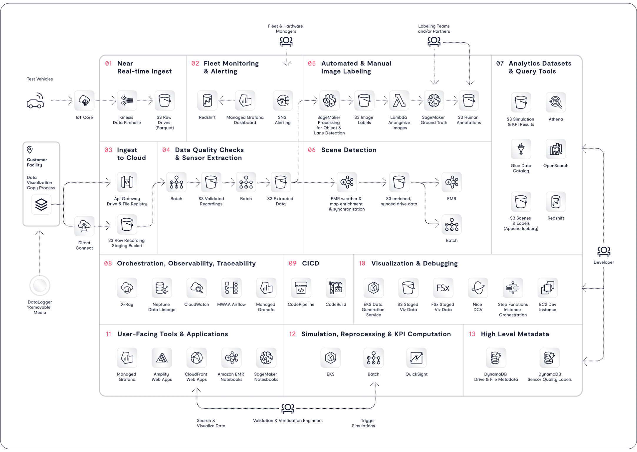
So – the divide between deep learning and data platforms is now clear and present. Why can’t today’s data platforms answer to the need of modern deep learning? Fundamentally, these systems were not designed to store and process the rich datatypes that are ingested from the natural world. Today’s popular data platforms were designed for modernized business reporting, not AI-driven automation. In truth, if the deep learning never existed – the adoption of today’s data platforms would be unchanged as these systems are primarily focused on data warehouse modernization. While these systems have been retrofitted to address some aspects of machine learning and deep learning use cases, fundamental gaps still exist.
Big Data Platforms | Deep Learning Requirements | |
Data Type | Structured & Semi-Structured Tables, JSON, Parquet | Unstructured Natural Data Text, Video, Instruments, etc. |
Processor Type | CPUs | GPUs, AI Processors & DPUs |
Dataset Size | TB-scale warehouses | TB-EB scale volumes |
Namespace | Single-Site | Globally-Federated |
Processing Paradigm | Data-Driven (Batch) | Continuous (Real-Time) |
The aim of the VAST Data Platform is to bridge this divide and to provide customers with the simple experience of today’s data platforms while also addressing the needs of deep learning applications where datatypes, data scale and data locality stretch far beyond the boundaries of today’s business reporting systems. By building an architecture that can store and organize exabytes of data and scheduling computational functions across a globally distributed set of AI supercomputers, the Platform’s north star points to a future beyond the relatively basic forms of Generative AI that we today see in use by Large Language Models.
The Promise of AI-Enabled Discovery
Yann LeCun, Chief AI Scientist at Meta and NYU Professor, recently characterized AI systems like ChatGPT as “students who have learned the material by rote but haven’t really built deep mental models of the underlying reality.”
While Generative AI and GPT models have taken the world by storm with their astonishing capabilities to respond to human prompts, this wave of artificial intelligence is unable to build complex mental models and is unable to reason about the nature of the data it has been trained with. This is, however, changing. As deep learning algorithms improve and as AI computers are scaled to even greater heights, we are now just starting to witness an early evolution that takes AI beyond recitation and into new domains of understanding and discovery.
For decades, computers have worked to automate many aspects of our daily lives, and AI-Enabled discovery is the final and hardest domain of AI-base automation will unfold over the next few decades. To learn as humans, we must give them the mechanisms to learn as we do in the natural world. The infrastructure foundation of this next wave of computing is the focus of the VAST Data platform, where we can envision mapping the methods that humans learn and discover against a computational platform. If you consider the advantage of building a global intelligent machine, it’s clear that the computational platform brings significant advantages that present the promise of radically accelerating the pace of discovery.
The Human Discovery Platform | The Computational Discovery Platform | |
Humans each have ~2PB of memory capacity | → | Single namespaces can now organize exabytes |
Humans take roughly 20 years to specialize in a specific research or professional domain | → | AI systems can be trained in minutes to be domain specialists |
There are a few 100,000 people who actually make an impact on discovery generationally | → | A global AI computer are now be built from trillions of AI processor cores |
Humans interact and learn through high-latency APIs such as email, meetings, reports, etc. | → | A global federation of systems can exchange information for cooperative or adversarial learning at the speed of the global internet. |
By building the engine of discovery, it is VAST’s hope that new forms of AI will advance our understanding of grand challenge problems that require new approaches to deliver significant benefit to society, accelerating our search for cures for disease, clean energy, solving the food crisis and more.
The VAST Data Platform
How It Works
The VAST Data Platform is a unified and containerized software environment that brings different aspects of functionality to different application consumers.
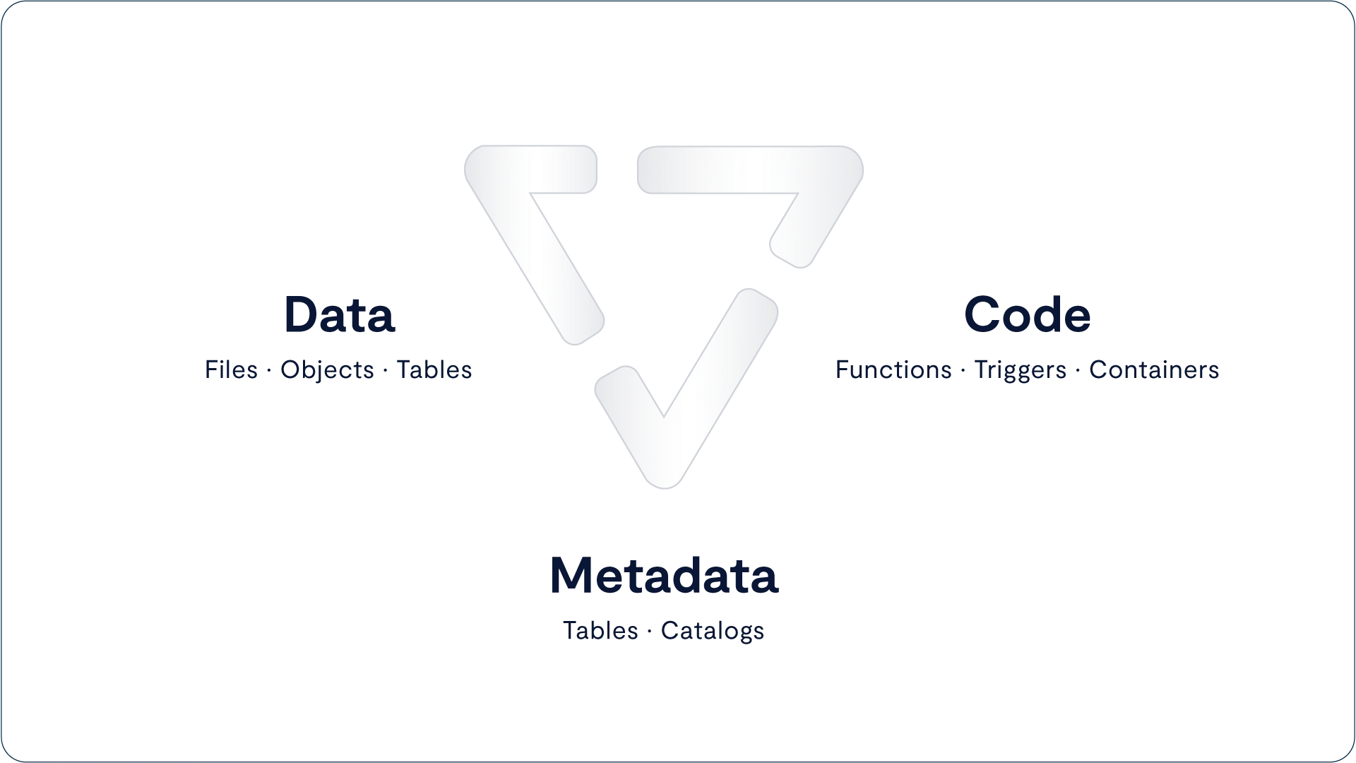
The system is the first data platform to bring together native support for tabular data (either written natively or converted from open formats such as Parquet), data streams and notifications that work with Kafka endpoints and unstructured data from high-performance enterprise file protocols such as NFS, SMB, and S3. By adding a serverless computing engine (supporting functions written in Python), the VAST Data Platform brings life to data by creating an environment for recursive AI computing. Data events become the functional application triggers that create opportunities for the system to catalog data, an event that may then trigger additional functions such as AI inference, metadata enrichment, and subsequent AI model retraining. By marrying data with code, the system can recursively compute on both new and long-term data, thus getting ever more intelligent by combining new interactions with past realizations in real-time.
Unlike batch-based computing architectures, the VAST architecture leverages a real-time write buffer to capture and manipulate data in real-time as it flows into the system. This buffer can intercept small and random write operations (such as an event stream or a database entry) as well as massively parallel write operations (such as application checkpoint file creations) all into a persistent memory space that is immediately available for retrieval and correlative analysis against the rest of the system’s corpus that is largely stored in low-cost hyperscale-grade flash-based archive storage. With a focus on deep learning, the platform works to derive and catalog structure from unstructured data, to serve as the foundation of automation and discovery harnessing data that is captured from the natural world.

The functional areas of the system break down into a few components which all combine into on Platform:
The VAST DataStore is the storage foundation of the Platform. Previously known as VAST’s Universal Storage offering, the DataStore is responsible for persisting data and making it available via all of the different protocols that applications may write or read from. The DataStore can be scaled to exabytes within a single data center, and is renowned for breaking the fundamental tradeoff between performance and capacity so that customers can manage their files, objects and tables on a single tier of affordable flash, thus making it ready for any-scale and any-depth data computing.
The DataStore’s ultimate purpose is to capture and serve the immense amount of natural raw, unstructured and stream data that is being captured from the natural world. The VAST DataBase is the system’s database management service that writes tables into the system and enables real-time, fine-grained queries into VAST reserves of tabular data and cataloged metadata. Unlike conventional approaches to database management systems, the VAST DataBase is transactional like a row-based OLTP database, from a columnar data structure that processes analytical queries like a flash-based data warehouse, and has the scale and affordability of a data lake.
The DataBase’s ultimate purpose is to organize the corpus of knowledge that lives in the VAST DataStore and to catalog the semantic understanding of unstructured data. The VAST DataEngine (shipping in 2024) is the system’s declarative function execution environment that enables serverless functions much like AWS Lambda and event notifications to be deployed in standard Linux containers. With a built-in scheduler and cost-optimizer, the DataEngine can be deployed on CPU, GPU and DPU architectures to leverage scalable commodity computing to bring life to data. Unlike classic approaches to computing, the DataEngine bridges the divide between event-based and data-driven architectures that enables you to stream into your systems of insight and derive real-time insight by analyzing and inferring and training against all of your data. The DataEngine’s ultimate purpose is to transform raw, unstructured data into information by inferring on and analyzing data’s underlying characteristics.
The VAST DataSpace then takes these concepts and extends them across data centers, building a unified computing fabric and storage namespace that is intended to break the classic tradeoffs of geo-distributed computing. The DataSpace provides global data access by synchronizing metadata and presenting data through remote data caches, but allows for each site to assume temporary responsibility for consistency management at extreme levels of namespace granularity (file-level, object-level, table-level). With this decentralized and fine-grained approach to consistency management, the VAST Data Platform is a global data store that ensures strict application consistency while also providing remote functions with high-performance. The DataSpace makes access easy, by eliminating islands of information while also keeping pipes full and keeping remote CPUs and GPUs busy by prefetching and pipelining data in an intelligent fashion. The DataEngine then layers on top of this namespace to create a flexible computational fabric that can route functions to the data (when data gravity is greater) or routes data to the function (when processing resources are scarce near the data). In this way, the DataSpace helps organizations fight against both processor and data gravity as they build global AI computing environments. The DataSpace’s ultimate purpose is to be the Platform’s interface to the natural world, extending access on a global basis and enabling federated AI training and AI inference.
Now that you have a basic idea what The VAST Data Platform is let’s see how well it fits what we identified earlier as requirements for big data and deep learning workloads:
Big Data | Deep Learning | VAST Data Platform | |
Data Types | Structured & Semi-Structured Tables, JSON, Parquet | Unstructured Text, Video, Instruments, etc. | Structured and Unstructured |
Processor Type | CPUs | GPUs, AI Processors & DPUs | Orchestrates across, manages CPU, GPU, DPU, etc. |
Storage Protocols | S3 | S3, RDMA file for GPUs | S3, NFSoRDMA, SMB |
Dataset Size | TB-scale warehouses | TB-EB scale volumes | 100 TB- EBs |
Namespace | Single-Site | Globally-Federated | Globally-Federated |
Processing Paradigm | Data-Driven (Batch) | Continuous (Real-Time) | Real-time and batch |
Architecting the VAST Data Platform
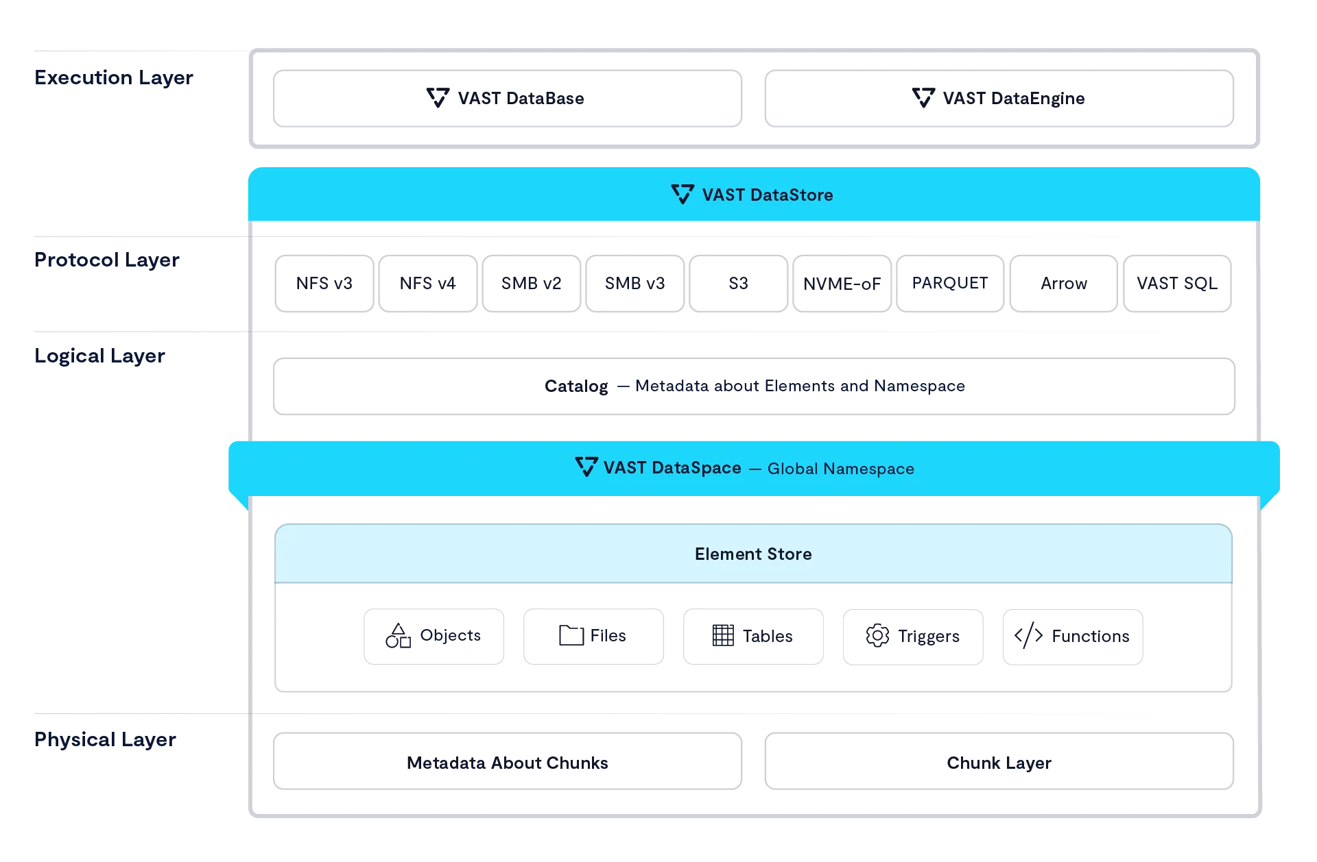
The VAST Data Platform is architected as a collection of service processes that communicate with outside clients and each other to provide a wide range of data services. The easiest way to explain these services and how they interact is to view them as providing layered services analogous to the seven layers of the OSI networking model.
However, unlike the OSI model, which defines a strictly layered architecture with clear boundaries between protocols at different layers, the VAST Data Platform layers are a tool of explanation; they do not represent hard boundaries. Some services may provide services across what would logically be a layer boundary, and services communicate across layers using non-public interfaces.
Starting from the bottom, because every architecture has to have a solid foundation, the layers of the VAST Platform are:
The VAST DataStore – The VAST DataStore is responsible for storing and protecting data across the VAST global namespace and making that data available both via traditional storage protocols and through internal protocols to The VAST DataBase and The VAST DataEngine. The VAST DataStore has three significant sub-layers:
The Physical or Chunk Management Layer provides basic data preservation services for the small data chunks the VAST Element Store uses as its atomic units. This layer includes services such as erasure-coding, data distribution, data reduction, encryption at rest, and device management.
The Logical Layer aka The VAST Element Store - Uses metadata to assemble the physical layer’s data chunks into the Data Elements like files, objects, tables and volumes that users and applications interact with and then organizes those Elements into a single global namespace across a VAST cluster and with The VAST DataSpace across multiple VAST clusters worldwide.
Like a file system after exposure to gamma rays The VAST Element Store organizes the physical storage layer’s chunks into a global namespace holding Elements such as file/objects, tables, and block volumes/LUNs. The VAST Element Store provides services at the Element or path level including access control, encryption, snapshots, clones, and replication. The Protocol Layer provides multiprotocol access to data Elements. All the protocol modules are peers providing full multiprotocol access to Elements as appropriate to their data type.
The Execution Layer - The execution layer provides and orchestrates the computing logic to turn data into insight through data-driven processing. The execution layer includes two major services:
The VAST DataBase – This service manages structured data. The VAST DataBase is designed to provide the transactional consistency required for OLTP (Online Transaction Processing), the data organization, and the complex query processing demanded by OLAP (Online Analytical Processing) at the scale required for today’s AI applications. Where the logical layer stores tables and the protocol layer provides basic SQL access to those tables, The VAST DataBase turns those tables into a full-featured database management system providing advanced database functions from sort keys to foreign keys and joins.
The VAST DataEngine – The VAST DataEngine adds the intelligence required to process, transform, and ultimately infer insight from raw data. The VAST DataEngine performs functions such as facial recognition, data loss prevention scanning, or transcoding on Elements based on event triggers like the arrival of an object meeting some filter or a Lambda function. The VAST DataEngine acts as a global task scheduler assigning functions to execute where the combination of compute resources, data accessibility, and cost best meet user requirements across a global network of public and private resources.
There’s nothing revolutionary about layered architecture; IT organizations have been running relational databases on top of SAN storage with orchestration engines like Kubernetes for years. The revolutionary parts of The VAST Data Platform are the tight integration between the services across the typical layer boundaries and the Disaggregated Shared Everything (DASE) cluster architecture those services run on.
The Disaggregated Shared Everything Architecture
The VAST Data Platform is software-defined, meaning it does all its magic in software running in containers on standard x86 and ARM CPUs. But that doesn’t mean the VAST DataPlatform was designed to run on a cluster of least-common-denominator x86 servers. By using the latest storage, and networking technologies like Storage Class Memory SSDs and NVMe over Fabrics (NVMe-oF), this Disaggregated Shared Everything (DASE) architecture allows VAST clusters to scale to unprecedented size. It breaks the tradeoffs inherent in the shared-nothing and shared-media models used in the past.
The DASE architecture introduces two revolutionary new concepts to data system cluster design.
Disaggregating the cluster’s computational resources from its persistent data and system state. In a DASE cluster, all the computation is performed by compute nodes (VAST Servers, sometimes called CNodes) that run in stateless containers. This very much includes all the computation needed to maintain the persistent storage that is traditionally performed by storage controller CPUs. This enables the cluster compute resources to be scaled independently from storage capacity across a commodity data center network.
A Shared-Everything model that allows any CNode to have direct access to all the data, metadata, and system state directly. In a DASE cluster, the system state is stored on NVMe SSDs in highly available NVMe JBOFs (Just a Bunch of Flash). These are known as storage enclosures or DBoxes (short for data box, but that was such a bad name we’re trying to forget it.) that connect the SSDs to the NVMe fabric.
Every CNode in a cluster mounts every SSD in the DASE cluster at boot time and thereby has direct access to the shared system state that provides a single, unpartitioned source of truth for everything from global data reduction to database transaction state.

From the key points and diagram above, you’ve probably figured out that the DASE architecture is based on two basic components: CNodes run that run all the software and DBoxes that hold all the storage media, and system state.
VAST Servers (CNodes)
VAST Servers, or CNodes, provide the intelligence to manage The VAST Data Platform. This includes protecting data in The VAST Element Store, processing database queries, and determining the best place to transcode a sports highlight to get it into the next replay video and processing that stream.
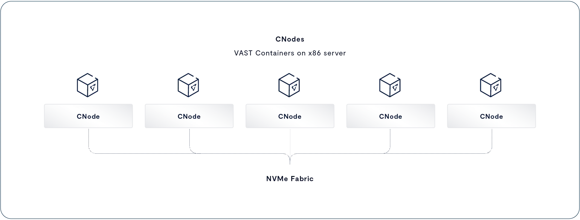
The VAST Data Platform runs as a group of stateless containers across a cluster of one or more x86 servers. The term CNode (for compute node) usually refers to the VAST server container running as a node in a VAST cluster. However, it can occasionally be used to mean the server the CNode runs on. If you ever see a reference like “Each CNode can use one 100 Gbps Ethernet card for both cluster internal traffic and connections to the client network,” it’s safe to assume CNode in that context means the server hardware the VAST CNode container runs on.
All the CNodes in a cluster mount all the SCM and hyperscale flash SSDs in the cluster via NVMe-oF at boot time. This means that every CNode can directly access all the data, and metadata, across the cluster. In the DASE architecture everything--every storage device, every metadata structure, the state of every transaction within the system--is shared across all the CNode servers in the cluster.
In a DASE cluster, nodes don’t own storage devices or the metadata for a volume. When a CNode needs to read from a file, it accesses that file’s metadata from SCM SSDs to find the location of the data on hyperscale SSDs and then reads the data directly from the hyperscale SSDs. There’s no need for that CNode to ask other nodes for access to the data it needs. Each CNode can process simple storage requests, such as read or write to completion, without having to consult the other CNodes in the cluster.
More complex requests like database queries and VAST DataEngine functions will be parallelized across multiple CNodes by the VAST DataEngine but we’ll talk about that when we talk about The VAST DataBase and The VAST DataEngine below.
Stateless Containers
The CNode containers that run the DASE cluster are stateless, meaning that any user request or background task that changes the state of the system, such as garbage collection or rebuilding after a device failure, is written to multiple SDDs in the cluster’s DBoxes before it is acknowledged or finally committed. CNodes do NOT cache writes, or metadata updates in DRAM, or even power-protected NVRAM. Where NVRAM appears safe, the contents of NVRAM are really only protected against power failures. Even then, data could be lost if the wrong two nodes fail, and the system must run special, and therefore error-prone, recovery routines to restore the data saved in the NVRAM on power failure.
The best demonstration of this happened a few years ago at a data center in the Boston area that houses HPC and research computing systems for many of the area’s universities. The data center suffered a power failure, and of the many storage systems housed there, only the VAST clusters simply returned to operation when power was restored. The other systems required their administrators and/or vendor support to take some action.
The ultra-low latency of the direct NVMe-oF connection between CNodes and the SSDs in DBoxes also relieves CNodes from maintaining read or metadata caches in DRAM as well. When a CNode needs to know where byte 3,451,098 of an Element is located, the metadata’s single source of truth for that information is just microseconds away. Because CNodes don’t cache, they avoid all the complexity and east-west, node-to-node traffic required to keep a cache coherent across the cluster.
Containers make it simple to deploy and scale The VAST Data Platform as software-defined microservices while also laying the foundation for a much more resilient architecture where container failures are non-disruptive to system operation. Legacy systems must reboot nodes to instantiate a new software version, which can take a minute or more as the node’s BIOS performs a power-on self-test (POST) on the node’s DRAM. The upgrade process for VASTOS instantiates a new VASTOS container without restarting the underlying OS, which reduces the time a VAST server is offline to a few seconds.
The combination of statelessness and rapid container updates allows VAST systems to perform all system updates from BIOS and SSD firmware re-flashes to simple patches non-disruptively, even for stateful protocols like SMB.
HA Enclosures (DBoxes)
All VAST Enclosures, also known as DBoxes (data boxes), are NVMe-oF storage shelves that connect SCM and hyperscale flash SSDs to an ultra-low latency NVMe fabric using Ethernet or InfiniBand. All HA Enclosures are highly redundant with no single point of failure – the DNodes that route NVMe over Fabrics requests between the NVMe fabric network and SSDs, NICs, fans, and power supplies are all fully redundant, making the clusters highly available regardless of whether they have one Enclosure or 1,000 HA Enclosures.
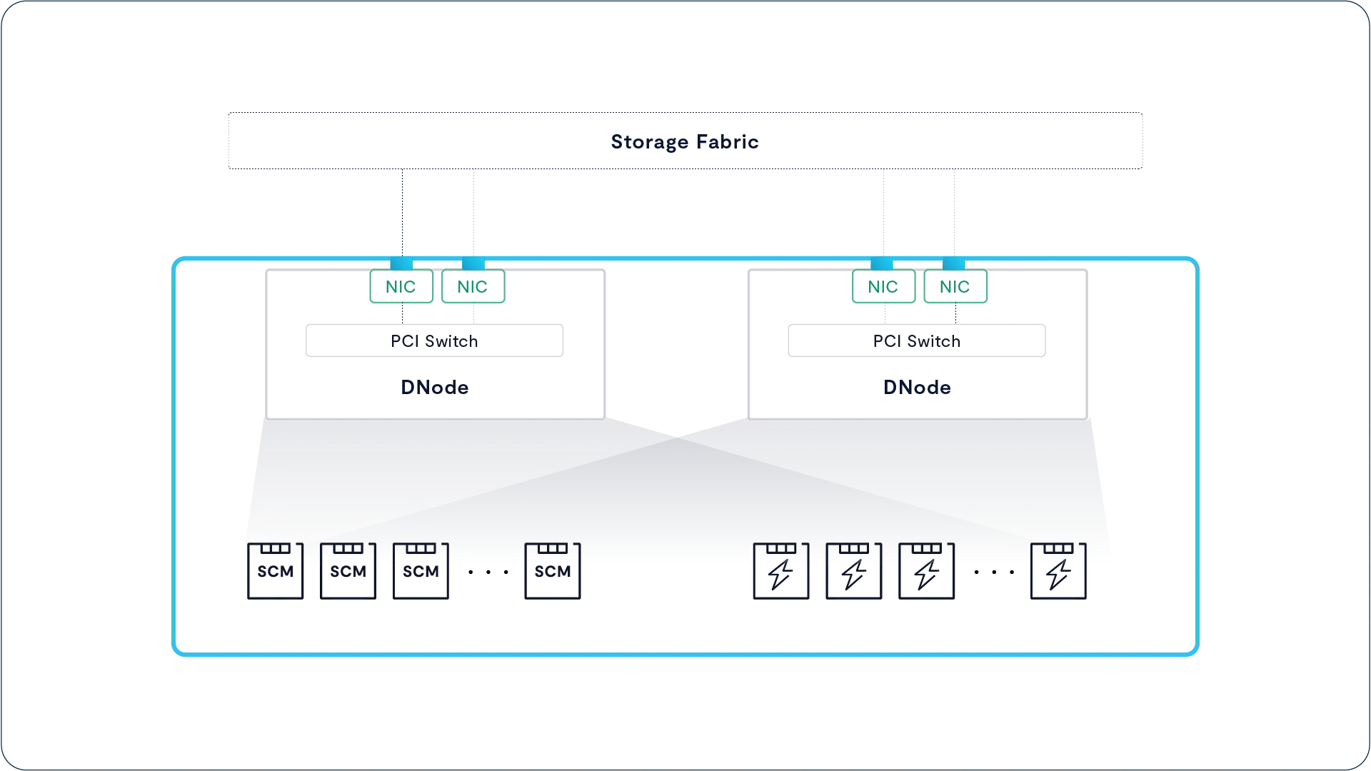
As you can see in the figure above, each HA Enclosure houses two DNodes that are responsible for routing NVMe-oF requests from their fabric ports to the enclosure’s SSDs through a complex of PCIe switch chips on each DNode.
With no single point of failure from network port to SSD, DBoxes combine enterprise-grade resiliency with high-throughput connectivity. While at face value the architecture of a DBox appears similar to a dual-controller storage array, there are, in reality, several fundamental differences:
DNodes do not execute any of the storage logic of the cluster; thus, their CPUs can never become a bottleneck as new capability is added to the VAST Data Platform.
Unlike legacy controllers, the DNodes don’t aggregate SSDs to LUNs or provide data services. Instead, these servers need little more than the most basic logic to present each SSD to the Fabric and route requests to/from SSDs within microseconds. One Gemini-supported enclosure, Ceres, consumes less power by using ARM DPUs as DNodes.
The two DNodes within a DBox run active-active. Under normal conditions, each DNode presents half the enclosure’s SSDs to the NVMe fabric. When a DNode goes offline, the surviving fabric module’s PCI switch remaps the PCIe lanes from the failed I/O module to the surviving DNode while retaining atomic write consistency.
Storage Class Memory
The term Storage Class Memory (SCM) defines a class of technologies that provide higher performance and endurance than commodity NAND flash, filling the gap between flash and DRAM in performance with a new, persistent layer.
The VAST DataStore leverages SCM SSDs both as a high-performance write buffer and as a global metadata store. SCM SSDs were chosen for their low write latency, and long endurance allows DASE clusters to extend the endurance of their hyperscale flash and provide sub-millisecond write latencies without the complexity of DRAM caching.
Each VAST cluster includes tens to hundreds of terabytes of SCM capacity, which provides the VAST DASE architecture with several architectural benefits:
Optimized Write Latency: VAST servers acknowledge writes to their clients after mirroring data to a buffer of ultra-low latency NVMe SCM SSDs. This buffer isolates application write latency from the time required to perform data services like global flash translation and data reduction while protecting applications from the high write latency of hyperscale SSDs.
Protects Low-Endurance flash from Transient Writes: Data can live in the SCM write buffer indefinitely, and because the buffer is so comparatively large, it relieves the hyperscale SSDs from the wear of many intermediate updates.
Data Protection Efficiency: The SCM write buffer provides the capacity to assemble many wide, deep stripes concurrently and write them in a near-perfect form to hyperscale SSDs in order to get 20x more longevity from these low-cost SSDs than classic enterprise storage write patterns can achieve.
Protects Low-Endurance flash from Aggressive Data Reduction: SCM enables the VAST Cluster to perform data reduction calculations after the write has been acknowledged to the application, but before the data is migrated to hyperscale flash – thus avoiding the write-amplification created by post-process approaches to data reduction.
Data Reduction Dictionary Efficiency: SCM acts as a shared pool of metadata that stores, among other types of metadata, a global compression dictionary that is available to all of the VAST Servers. This allows the system to enrich data with much more data reduction metadata than classic storage can (to further reduce infrastructure costs) while avoiding the need to replicate a data reduction index into the RAM space of every VAST Server (a classic problem with deduplication appliances).
Hyperscale Flash
Hyperscale flash refers to the types of SSDs used by hyperscalers like Facebook, Google, and Baidu to minimize flash costs. Because hyperscalers build their systems very differently from enterprise SAN arrays, hyperscale SSDs are different from both enterprise and consumer SSDs.
Enterprise SSDs are designed for enterprise SAN arrays where dual-port drives have long been connected to dual controllers and to deliver consistently low write latency. That means enterprise SSDs need expensive components like dual-port controllers, DRAM caches, and power protection circuitry, along with flash overprovisioning to manage endurance for the 4KB random-write-heavy JEDEC testing regime.
The hyperscalers build storage systems from servers that can only connect to one port on an SSD, only writing large objects, and therefore don’t need dual ports, a DRAM cache, or much overprovisioning. Hyperscale SSDs make flash affordable by using the densest available flash--currently four-bit per cell QLC--and delivering that capacity directly to storage.
Squeezing another bit into each flash cell boosts capacity, and since it doesn’t significantly increase manufacturing costs, it brings the cost per GB of flash down to unprecedentedly low levels. Unfortunately, squeezing more bits in each cell has a trade off. As each successive generation of flash chips reduced cost by fitting more bits in a cell, each generation also had lower endurance, wearing out after fewer write/erase cycles. The differences in endurance across flash generations are huge – while the first generation of NAND (SLC) could be overwritten 100,000 times, QLC endurance is 100x lower. As flash vendors promote their upcoming PLC (Penta Level Cell) flash that holds 5 bits per cell, endurance is projected to be even lower.
Erasing flash memory requires high voltage that causes damage to the flash cell’s insulating layer at a physical level. After multiple cycles, enough damage has accumulated to allow some electron leakage through the silicon’s insulating layer. This insulating layer wear is the cause of high bit density flash’s lower endurance. For a QLC cell, for example, to hold a four-bit value; it must hold one of 16 discrete charge/voltage levels, all between 0 and 3 volts or so. Holding that many bits as slightly different voltage levels makes QLC more sensitive to electron leakage through the insulating layers. As the number of bits that have to be represented by a voltage between 0 and 3 volts increases, the difference between one value and another shrinks, making each generation of flash more sensitive to the escape of a few electrons from a cell. This allows low bit density flash to absorb more damaging erase cycles before leakage changes a 1 to a 0 or vice versa.
VAST’s Universal Storage systems were designed to minimize flash wear in two ways: first, by using innovative new data structures that align with the internal geometry of low-cost hyperscale SSDs in ways never before attempted; and second, by using a large SCM write buffer to absorb writes, providing the time, and space, to minimize flash wear. The combination allows VAST Data to support our flash systems for 10 years, which has its own impact on system ownership economics.
Asymmetric Scaling
Legacy scale-out architectures aggregate computing power and capacity into either shared-nothing nodes with a single “controller” per node or shared-media nodes with a pair of controllers and their drives. Either way, users are forced to buy computing power and capacity together across a limited range of node models while balancing the cost, performance, and data center resources needed by a small number of large nodes vs. a larger number of nodes with less capacity per node.
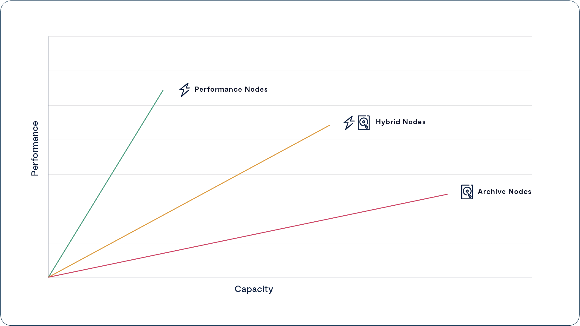
The DASE architecture eliminates these limitations as the simple result of disaggregating a VAST system’s computing power into CNodes that are independent of the DBoxes that provide capacity. VAST customers training their AI models (a workload that accesses a large number of small files) or processing complex queries using The VAST DataBase will use as many as a dozen CNodes per DBox. At the other extreme, customers using their VAST clusters to store backup repositories, archives, and other less active datasets typically run their clusters with less than one CNode per DBox.
When a VAST customer needs more capacity, they can expand their VAST cluster by adding more DBoxes without the cost (and not insignificant power consumption) of adding more compute power. This is a feature of old-school scale-up storage systems the scale-out vendors abandoned.
Expanding capacity alone is cost-effective, and old-school cool, but the only path legacy vendors ever provided to increase the amount of computing power in a cluster for a given capacity was to use a forklift to install new faster nodes, or add more nodes with smaller drives which also boosts the CPU power per Petabyte.
When VAST customers discover their new AI engine can extract value from what they thought was a cold archive, or the new version of their key application starts performing a lot more small random I/Os than the old one, or simply that their new application is more popular across the company than the thought it would be, they can add more computing power to their cluster by adding more CNodes. The system will automatically rebalance VIPs (Virtual IP Addresses) and processing across the new CNodes when they’re added to a pool.
Asymmetric and Heterogeneous
Shared-nothing users face a difficult challenge when their vendors release a new generation of nodes. Because all the nodes in a storage pool have to be identical, a customer with a 16-node cluster of 3-year-old nodes who needs to expand capacity by 50% faces two choices:
Buy 8 additional nodes and extended support for the current 16 nodes
Extended support only available for total 5 or 6 years so replacement of all 24 nodes will be required in 2-3 years
Buy 5 new model nodes with twice the density and create a new pool
Performance will depend on pool data is in
Multiple pools add complexity
Lower efficiency from small cluster
This gets especially dicey when new features, like inline deduplication and compression, require the faster processor of the new model nodes.
When we say that DASE is an asymmetric architecture, we don’t just mean that customers can vary the computing power per petabyte of their systems by adjusting the number of servers (CNodes) per storage enclosure (DBox), or petabyte. Asymmetric also means that DASE systems support asymmetry across the servers running the VAST CNode containers, DBoxes, and the SSDs inside those enclosures.
VAST systems accommodate CNodes with different numbers or speeds of cores by treating the CNodes in a cluster as a pool of computing power scheduling tasks across the CNodes the way an operating system schedules threads across CPU cores. When the system assigns background tasks, like reconstructing data after an SSD failure or migrating data from the SCM write buffer to hyperscale, flash tasks are assigned to the servers with the lowest utilization. Faster CNodes will be capable of performing more work and will therefore be assigned more work to do.
DASE systems similarly manage the SSDs in the cluster as pools of available SCM and hyperscale flash capacity. Every CNode has direct access to every SSD in the cluster, and the DNodes provide redundant paths to those SSDs, so the system can address SSDs as independent resources and failure domains.
When a CNode needs to allocate an SCM write buffer, it selects the two SCM SSDs that have the most write buffer available and are as far apart as possible, always connected to the fabric through different DNodes, in different DBoxes if the system has more than one. Similarly, when the system allocates an erasure-code stripe on the hyperscale flash SSDs it selects the SSDs in the cluster with the most free capacity and endurance for each stripe.
Since SSDs are chosen by the amount of space and endurance they have remaining, any new SSDs or larger SSDs in a cluster will be selected for more erasure-code stripes than the older, or smaller SSDs until the wear and capacity utilization equalize across the SSDs in the cluster. See A Breakthrough Approach To Data Protection below for more details.
The result is that VAST customers are never faced with choosing between buying a little more of the old technology they’re already using, knowing these nodes will have a short working life, or replacing the whole cluster even though their current nodes have a few more years of life. When a VAST customer’s cluster requires more compute power, they don’t have to upgrade all their nodes to the new model with a faster processor; instead, they can just add a few CNodes.
VAST guarantees to support clusters with as many as three generations of hardware and to support any VAST-branded CBox or DBox for up to 10 years under Gemini. This allows VAST customers to run VAST clusters for long periods of time by adding new hardware and retiring old hardware from the cluster. In any case, data, and work are balanced automatically and transparently, eliminating not just the forklift but all the drama from upgrades.
Server Pooling
In the DASE architecture, VAST Servers provide the computing power to run the VAST Data Platform’s various services and the connections from the cluster to the rest of the network. VAST users can subdivide the VAST Servers in their cluster into multiple pools for several reasons:
Provide connections to disparate network technologies. Customers can provide access to their VAST cluster from their HPC cluster over Infiniband through a pool of CNodes with IB cards and Ethernet access from the rest of their infrastructure through a second pool with 100 Gbps Ethernet NICs.
Provide network isolation. VAST operators can limit access to tenants and Views (multiprotocol shares/exports/buckets) by IP address pools limiting access to data by location and server pool access.
Dedicate performance to user groups, applications, or services. Users can provide dedicated performance by building pools of CNodes for different applications, users, or service pools as an affirmative form of quality of service.
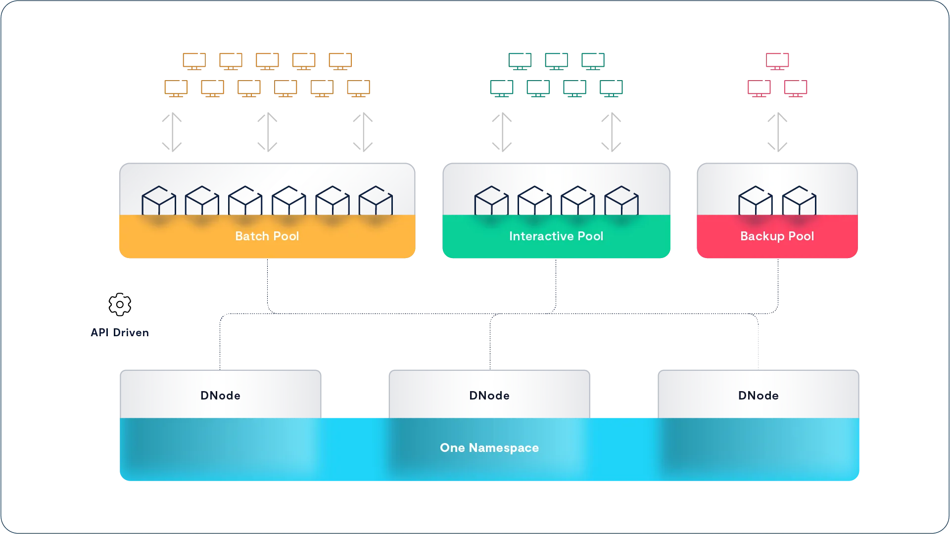
The VAST cluster in the picture above is configured with three server pools: a server pool to support their batch or, more accurately, continuous applications, a pool to provide dedicated performance for their interactive users, and a pool for their backup applications. These pools ensure that the interactive users get enough performance to keep them happy and that the batch and backup processes don’t interfere with each other.
Sophisticated users, such as an animation studio, can even move servers (CNodes) from one pool to another through scripts, or VAST Data Engine Functions, providing enough compute power for their temperamental artists during the day and transferring CNodes to the render farm pool as artists log out at night to maximize render performance.
Server (CNode) pooling provides an affirmative QoS (Quality of Service) mechanism through the number of servers assigned to each pool. The VAST DataStore also provides a declarative QoS method: see “QoS Silences Noisy Neighbors” in the VAST Element Store section of this eWhitePaper.
Each server pool has an assigned set of VIPs (Virtual IP Addresses) that are distributed across the CNodes in the pool. When a CNode goes offline, the VIPs it was serving are redistributed across the remaining members of the pool. VAST recommends users configure each pool with 2-4 times as many VIPs as CNodes so the load of a CNode being taken offline can be distributed across multiple other CNodes in the pool.
Each CNode can be a member of multiple server pools so a CNode can serve user requests while also replicating data between DASE clusters.
Networking in DASE
A DASE cluster includes four primary logical networks.
The NVMe fabric, or back-end network, connects CNodes to DNodes. VAST clusters use NVMe over RDMA for CNode<->DNode communications over 100 Gbps Ethernet or InfiniBand with Ethernet as the default.
The host network, or front-end network, that carries file, object, or database requests from client hosts to the cluster’s CNodes.
The management network that carries management traffic to the cluster, including DNS and authentication traffic.
The IPMI network used for managing and monitoring the hardware in the cluster.
Depending on their requirements, VAST customers have several options for how to implement these logical networks using dedicated ports, and/or VLANs as their network designs and security concerns dictate. The biggest decision is how the DASE cluster is connected to the customer’s data center network to provide host access.
Connect via Switch

The Connect via Switch option runs the NVMe back-end fabric and the front-end host network connections as two VLANs on the NVMe fabric switches that are included in each DASE cluster. The customer’s host network is connected to the cluster through an MLAG connection from the fabric switches to the customer’s core switches as shown in green above.
Each CNode has a single 100 Gbps network card. A splitter cable turns that into a pair of 50 Gbps connections, one for each of the two fabric switches. Each 50 Gbps connection carries NVMe fabric traffic on one VLAN and host data traffic on another.
The Connect via Switch method has several advantages:
Only one RNIC is needed in each CNode
Network traffic is aggregated to a small number of 100 Gbps links MLAGed together minimizing the number of host network switch ports needed
If Connect via Switch was perfect we wouldn’t have any other options, but there are disadvantages:
Host network connections must be the same as the fabric
Infiniband fabrics only support Infiniband hosts
40, 25, 10 Gbps Ethernet connections expensive in 100 Gbps fabric ports
Only one physical host network
Connect via CNode
Connecting DASE clusters to the customer’s network through the NVMe fabric switches is simple, and minimizes the number of network ports. But as we discussed in the server pooling section above, customers may need more flexibility or control over how their various clients and tenants should connect to their DASE cluster.

When VAST customers need to connect clients from multiple disparate networks with different technologies, or security considerations, they can solve that problem by connecting those networks to CNodes with a second network card that connects directly to the network that CNode will serve.
Advantages of Connect via CNode
Connect hosts to the DASE cluster via different technologies
Infiniband clients served by CNodes with Infiniband NICs
Ethernet clients served by CNodes with Ethernet NICs
Or Ethernet clients connected via fabric switches
Support for new technologies like 200 Gbps Ethernet for client connect
Connect multiple security zones w/o routes
Disadvantages
Requires more network cards, switch ports, IP Addresses, etc.
As noted in the advantages section above, VAST customers are free to mix the “connect via CNode” and “connect via switch” models. A customer with a few Infiniband hosts could install IB cards in one pool of CNodes and still connect their Ethernet clients to the DASE cluster through the Ethernet fabric switches to minimize the number of switch ports needed.
Leaf-Spine for Large Clusters
As DASE clusters grow to need more NVMe fabric connections than a pair of 64-port switches can provide, the pair of fabric switches usually shown at the core of a DASE cluster grows into a leaf-spine network. The CBoxes (multi-server chassis running multiple CNodes in a single appliance) and DBoxes are still connected to a pair of switches, but instead of that top-of-rack switch pair being the core of the cluster they become leaves redundantly connected to a pair of Spine switches, as are the leaf switches at the top of the other racks of the cluster.
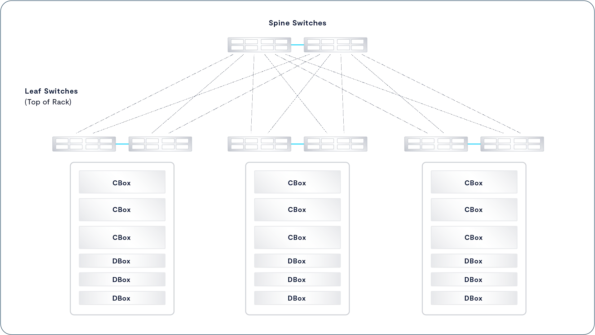
Leaf-spine networking allows DASE clusters to grow to well over 100 appliances, especially when large port count director class switches are used in the spine. Planning is underway for very large clusters of 1,000 appliances or more, so the groundwork will be laid before customers reach that size.
Scale-Out Beyond Shared-Nothing
For the past decade or more, the storage industry has convinced itself that a shared-nothing storage architecture is the best approach to achieving storage scale and cost savings. Following the release of the Google File System architecture whitepaper in 2003, it became table stakes for storage architectures of almost any variety to be built from a shared-nothing model, ranging from hyper-converged storage to scale-out file storage to object storage to data warehouse systems and beyond. Ten years later, the basic principles that shared-nothing systems were founded on are much less valid for the following reasons:
Shared-nothing systems were designed to co-locate disks with CPUs, in an era when networks were slower than local storage. However, with the advent of NVMe-oF, it’s now possible to disaggregate CPUs from storage devices without compromising performance while accessing SSDs and SCM devices remotely.
Shared-nothing systems force customers to scale compute power and capacity together, creating an inflexible infrastructure model vs. being able to scale up CPUs as the data set needs faster access performance.
Shared-nothing systems limit storage efficiency. Since each node in a shared-nothing cluster owns some set of media, a shared-nothing cluster must accommodate node failures by erasure-coding across nodes, limiting stripe width and shard, or replicate data reduction metadata, limiting data reduction efficiencies. Shared-everything systems can build wider, more efficient RAID stripes when no one machine exclusively owns any SSDs and build more efficient global data reduction metadata structures.
As containers become an increasingly popular choice for deploying applications, this microservices approach to deploying applications benefits from the stateless approach containers bring to the table, making it possible to easily provision and scale data services on composable infrastructure when data locality is no longer a concern.
The Advantages of a Stateless Design
When a VAST Server (CNode) receives a read request, that CNode accesses the VAST DataStore’s persistent metadata from shared Storage Class Memory to find where the data being requested actually resides. It then reads that data directly from hyperscale flash (or SCM if the data has not yet been migrated from the write buffer) and forwards the data to the requesting client. For write requests, the VAST Server writes both data and metadata directly to multiple SSDs and then acknowledges the write.
This direct access to shared devices over an ultra-low latency fabric eliminates the need for VAST servers to talk with each other to service an IO request – no machine talks to any other machine in the synchronous write or read path. Shared-Everything makes it easy to linearly scale performance just by adding CPUs and thereby overcome the law of diminishing returns that is often found when shared-nothing architectures are scaled up. Clusters can be built from thousands of VAST servers to provide extreme levels of aggregate performance. The primary limiter on VAST cluster scale is the size of the network fabric that customers configure.
Storing all the system’s metadata on shared, persistent SSDs across an ultra-low latency fabric eliminates the need for CNodes to cache metadata and, therefore, any need to maintain cache coherency between Servers/CNodes. Because all data is written to persistent SCM SSDs before being acknowledged to the user, not cached in DRAM, there’s no need for the power failure protection hardware usually required by volatile and expensive DRAM write-back caches. VAST’s DASE architecture pairs 100% nonvolatile media with transactional storage semantics to ensure that updates to the Element Store are always consistent and persistent.
The DASE architecture eliminates the need for storage devices to be owned by one, or an HA pair, of node controllers. Since all the SCM and hyperscale flash SSDs are shared by all the CNodes, each CNode can access all the system’s data and metadata to process requests from beginning to end. That means a VAST Cluster will continue to operate and provide all data services even with just one VAST Server running. If, for example, a cluster consisted of 100 servers, said cluster could lose as many as 99 machines and still be 100% online.
The VAST DataStore
Storage, the basic ability to reliably store and retrieve data, is the foundation of any data processing system and that makes the VAST DataStore the foundation of the whole VAST Data Platform. After all, the first job of any data platform is to store the data.
The VAST DataStore provides the persistence and data services layers of the VAST Data Platform. In English, that means that the VAST DataStore is responsible for storing, protecting, securing, and presenting the data in the VAST Data Platform using standard data access protocols (file, object, and block), providing Universal Storage for the rest of the VAST Data Platform, and other workloads.
Designing the VAST DataStore
Before VAST, the computing world assumed that the only way to efficiently store data was with multiple tiers of storage, each providing a unique price/performance proposition. Storage vendors built, and storage users bought, storage systems designed to fit one or two tiers in the storage pyramid. All-flash systems were fast but small and expensive; shared-nothing systems scaled but couldn’t handle small files or deliver 1 ms latency.
For the VAST DataStore to truly deliver universal storage, we had to build a system that broke all the tradeoffs underlying previous solutions. It had to scale to the exabytes of data needed to train the most advanced AI models while still delivering the sub to single digit millisecond latency and five 9s reliability users expect from an all-flash array. It had to support parallel I/O from thousands of clients and deliver the strict atomic consistency to support transactional applications. Perhaps most importantly, it had to do it all at a price customers could afford when buying petabytes at a time.
The VAST DataStore is the software and the metadata structures that turn the CNodes and SSDs of a DASE cluster into a coherent storage system that provides universal storage. It supports a wide range of applications and data types, from volumes to files and tables. The VAST DataStore takes full advantage of the low-latency direct connection from every CNode to every SSD in the cluster by optimizing metadata structures for the shared, persistent SCM SSDs.
Unlike first generation all-flash arrays that provided low latency across limited capacities, the VAST DataStore was designed to manage petabytes to exabytes of data efficiently. This doesn’t just mean efficient use of capacity through erasure codes and data reduction, though those are an important part of the VAST DataStory (Sorry I couldn’t resist the pun); it also means the efficient management of flash endurance.
The VAST DataStore manages data through two sublayers:
The Physical or Chunk Management Layer provides the basic data preservation services for the small (32 KB average) data chunks the VAST Element Store uses as its atomic units. This layer includes services such as erasure-coding, data distribution, data reduction, flash management, and encryption at rest.
The VAST Element Store organizes the Elements stored and protected by the Element Management Layer into Elements such as files, objects, tables, and LUNs. This layer provides element-level protocol access and element- or path-based services such as snapshots, clones, and replication, including the Constellation global namespace.
These two layers work together to provide a next-generation datastore designed to:
Scale to exabytes while providing all-flash performance and hard drive economics
Provide a single namespace that natively accommodates a wide range of data elements including files, objects, block volumes, and tables, eliminating the need for gateways and protocol translations
Provide a full set of data services including zero-write snapshots and flexible replication
Use the SCM provided by VAST as single source of truth for system state and metadata
Provide strict ACID consistency for data and metadata updates
Minimize flash wear via predictive placement and write shaping
Provide the highest level of resilience (n+4) with less than 3% overhead, breaking the traditional tradeoffs between efficiency, performance, and cost
Remember, the layered structures we describe in this whitepaper don’t have the strict boundaries the layered description may imply. The physical and Element Store layers share common metadata structures, and some system tasks or data services may straddle the logical boundaries between layers. This fuzziness is most apparent when we talk about table elements that are stored by the VAST DataStore but managed and accessed through the VAST DataBase.
Defining the DataStore
A New Approach to Metadata
While it’s a bit of an oversimplification, you can think of the VAST Element Store as an Über-File System (Nietzsche not rideshare) that presents files, tables, volumes, event triggers, functions and objects all with equal aplomb. The VAST Element store is of course tightly coupled to the physical layer using byte-oriented metadata.
While it’s not often discussed, modern storage features are based on metadata. These features include thin provisioning, snapshots, clones, and data deduplication. We’ve seen many times that data layout and metadata structure decisions made when a system is initially designed can have a big impact on the system’s feature set down the road.
The most important task of any data store is maintaining a consistent view of the data so users and applications get the data they should when they issue a read. Eventual consistency may be good enough for some applications, but real data processing requires strictly consistent data. Before we dig into how the VAST DataStore organizes data, let’s look at how it maintains that consistency.
Inherently Persistent
All the VAST DataStore’s metadata, from basic file names to multiprotocol ACLs and locks, is maintained on shared media in VAST enclosures. This allows the mirrored and distributed metadata to serve as a consistent single source of truth regarding the state of the Element Store.
Eliminating the need for server-side caching also eliminates the overhead, and once again complexity, of keeping cached data coherent across multiple storage controllers. VAST systems store all their system state in shared enclosures that are globally accessible to each server over NVMe-oF. Because each VAST Server directly accesses a single source of system state, they don’t need to create any east-west traffic between nodes that shared-nothing systems require to update each other’s caches. This has two significant advantages:
Since the Storage Class Memory that the metadata is stored on is inherently persistent, there’s no data in DRAM or NVRAM cache. Destaging data from a volatile cache is often the largest contributing factor to enterprise storage data loss – as cache management and graceful destaging are simply difficult problems to solve. VAST Datastore avoids this issue altogether (even while providing support for exceptionally large and efficient write stripes). And because there’s no cache, there’s also no need for power-failure protection such as batteries (which need to be periodically changed) or expensive ultra-capacitors.
Without the need to coordinate caches, it is much easier to scale I/O services across a scale-out namespace. The VAST Datastore architecture eliminates the need for east-west traffic in the synchronous write and read path, thus eliminating a number of operations that would otherwise need to be coordinated across the cluster (metadata updates, lock management, etc.). As server CPUs are added, the cluster benefits from a linearly scalable increase in performance – whereas other systems frequently experience the law of diminishing returns as global update operations need to be shared across an increasingly larger number of nodes.
Transactionally Consistent
Because we were designing the VAST DataStore to hold tables as well as files and objects, we knew we’d have to marry the transactional guarantees of an ACID database with the performance of a parallel file system and the scale of an object store. To achieve this goal, VAST Data needed to create a new distributed transaction model, with hybrid metadata structures that combine consistent hashing and tree-oriented metadata with a log influenced write in free space data layout, new locking, and transaction management techniques.
At its core, the DataStore manages its metadata across a shared pool of Storage Class Memory with a V-Tree holding each element’s (file, object, folder, Table, Volume, etc) metadata. CNodes locate the root of each element’s V-Tree using consistent hashing of each element’s unique handle. The hash space is divided into ranges, with each range assigned to two of the cluster’s enclosures. Those two DBoxes then hold the metadata roots for elements whose handles hash to values in ranges they are responsible for.
VAST Servers load the 1 GB consistent hash table into memory at boot. When a VAST Server wants to find data within a particular file or object, it calculates the hash of the element’s handle, and performs a high-speed memory lookup to find which enclosure(s) hold that element’s metadata by hash range. The VAST Server can then read the element’s V-Tree from one of the DBoxes responsible for that portion of the hash space.
By limiting the use of consistent hashing to only the root of each data element, the dataset size per each hash table is very small – the system scales while minimizing the amount of hash data that has to be recalculated when VAST clusters expand. When a new enclosure is added to a cluster, it assumes ownership of its share of the consistent hash space and only the metadata from those buckets migrated to the new enclosure.
V-Trees for Fast Access
The VAST DataStore maintains its persistent metadata in V-Trees. VAST’s V-Trees are a variation of a B-tree data structure, specifically designed to be stored in shared, persistent memory. Because VAST Servers are stateless, a new metadata structure was needed to enable them to quickly traverse the system’s metadata stored on remote SCM devices. To achieve this, VAST designed a tree structure for extremely wide fan-out: each node in a V-Tree can have 100s of child elements – thus limiting the depth of an element search and the number of round trips over the network to no more than seven hops.
VAST Servers do not, themselves, maintain any local state – thereby making it easy to scale services and fail around any Server outage. When a VAST Server joins a cluster, it executes a consistent hashing function to locate the root of various metadata trees. As Server resources are added, the cluster leader rebalances responsibility for shared functions. Should a Server go offline, other Servers easily adopt its VIPs and the clients will connect to the new servers within standard timeout ranges upon retry.
While it isn’t organized in tables, rows, and columns, the DataStore’s V-Tree architecture enables the metadata store to act in many ways like a database – allowing VAST Servers to perform queries in parallel and locate, for example, an object in an S3 bucket, or the same data as a file, as it existed when the 12.01 AM January 1, 2024 snapshot was taken.
Just as CPUs add a linearly scalable unit of capacity, DataStore metadata is distributed across all the cluster’s Storage Class Memory which enables the namespace to scale as well enabling performance to scales as more and the VAST Cluster scales.
Database Semantics
VAST DataStore’s namespace metadata can be thought of in some ways as a database against which the system makes queries to locate pieces of data by file or object name, snapshot time, and other metadata attributes. That database metaphor also extends to how the VAST DataStore uses transactional semantics to ensure that the VAST DataStore, like a relational database, is fully ACID (Atomic, Consistent, Isolated, Durable).
Unlike eventually-consistent systems (such as object storage), the VAST DataStore provides a consistent namespace through all the VAST Servers in a cluster to all the users. Changes made by a user on one node are immediately reflected and available to all other users.
To remain consistent, the VAST DataStore ensures that each transaction is atomic. To achieve this, each storage transaction is either applied to the metadata (and all of its mirrors) in its entirety, or not applied to the metadata at all (even if a single transaction updates many metadata objects). With atomic write consistency, classic file system check tools (such as the dreaded fsck) are no longer needed, and systems can be instantaneously functional upon power cycle events.
Transaction Tokens
VAST V-Tree update transactions are managed using transaction tokens. When a VAST Server initiates a transaction, it creates a transaction token metadata object, and increments the transaction token counter. The transaction token contains a globally unique identifier that is accessible from all VAST servers and is used to track updates across multiple metadata objects. This token is infused with the identity of the VAST Server that owns the transaction as well as the transaction’s state (ongoing, canceled, committed), for purposes of enabling the system to avoid complications from parallel operations.
As the VAST Server writes changes to the V-Tree, it creates new metadata objects with the transaction token attached. When another VAST Server accesses an element’s metadata, it checks the transaction token state and then takes the appropriate action using the latest data for committed transactions. If a VAST Server (requesting Server) wants to update a piece of metadata that is already part of an in-flight transaction, it will poll the owning Server to ensure it’s still operational and will subsequently stand down until the owning server completes the in-flight transaction. If, however, a requesting Server finds in-flight data that is owned by another non-responsive owning Server, the requesting Server will access the consistent state of the namespace using the previous metadata and can also cancel the transaction and remove the metadata updates with that token.
Bottom-Up Updates
One key to designing a high-performance transactional namespace is to minimize the exposure to failure during any given transaction by minimizing the number of steps in a transaction that could cause the namespace to be inconsistent if the transaction didn’t complete. The VAST DataStore minimizes this exposure by making its updates from the bottom of the V-Tree and working up. When a client overwrites data in an existing file, the system performs the following steps (simplified for the purposes of this document):
Data is written to free space on mirrored Storage Class Memory SSDs (via indirection)
Metadata objects and attributes are created (BlockID, life expectancy, checksum)
The file’s metadata is changed to link to any new metadata objects
This new write is then, and only then, acknowledged to the client
For operations that fail before step #4 is successfully completed, the system will force clients to retry a write and any old/stale/disconnected metadata that remains from the previous attempt will be handled via a background scrubbing process.
If, by comparison, the system updated its metadata from the top down, that is first add a new extent to the file descriptor followed by the extent, and block metadata; a failure in the middle of the transaction would result in corrupt data from pointers to nothing. Such a system would have to treat the entire change as one complex transaction, with the file object locked the whole time. Updating from the bottom, the file only has to be locked when the new metadata is linked in (3 writes vs. 20). Shorter locks reduce contention and therefore improve performance.
Element Locking
While each read operation within the metadata store is lockless, the VAST cluster employs internal write locks to ensure parallel write consistency across the namespace. Element Locks differ from Transaction Tokens in that Transaction Tokens ensure consistency during Server failure; Element Locks ensure consistency while multiple writers attempt to operate on a common range of data within the DataStore.
Metadata locks, as with Transaction Tokens, are signed with the ID of the VAST Server that reserved a lock. When a VAST Server discovers a metadata object is locked, it contacts the server identified with the lock, while preventing zombie locks, without the bottleneck of a central lock manager. If the owning Server is unresponsive, the requesting Server will also ask another non-involved Server to also poll the owning Server as a means to ensure that the requesting Server does not experience a false-positive and prematurely fail an owning Server out of the VAST Cluster.
To ensure that write operations are fast, the VAST Cluster holds read-only copies of Element Locks in the DRAM of the VAST Enclosure where the relevant Element lives. In order to quickly verify an Element’s lock state, a VAST Server performs an atomic RDMA operation to the memory of an Enclosure’s Fabric Module to verify and update locks.
While the above Locking semantics apply at the storage layer, the VAST Cluster also provides facilities for byte-granular file system locking that is discussed later in this document (see: VAST Datastore: Protocols).
The Physical Chunk Management Layer
The Physical or chunk management layer of the VAST DataStore performs many of the same functions that a SAN array or logical volume manager (LVM) does in conventional architectures, protecting data against device failures and managing the storage devices.
While the physical layer, like RAID, is responsible for persisting and maintaining data written to the VAST DataStore, the methods it uses, like locally decodable erasure codes, have come a long way from the days of RAID. The other big difference is that the VAST DataStore uses one integrated set of metadata to manage the namespace of elements (files/objects/Tables/etc) and the datachunks so it can make smarter decisions when placing data.
Previous storage and file systems were designed to minimize random I/O, because hard drives could only perform a few IOPS each by caching metadata in controller DRAM. This not only created complexity to keep this distributed cache coherent, but the limited amount of DRAM forced file system architects to simplify their metadata in several ways.
They allocated space and reduced and protected data in fixed-size allocation blocks, forcing tradeoffs between the advantages of small or large blocks for different purposes and limiting the effectiveness of their compression
They limited scale with intermediate abstractions like RAID sets, volumes, and file systems, which created fragmented namespaces
They replicated or erasure-coded file by file instead of globally, complicating the management of small files and data reduction
The VAST DataStore was designed for the DASE architecture, and since DASE clusters have no spinning disks there’s no need to optimize I/O to be sequential. Instead, the VAST DataStore is optimized for low-cost hyperscale flash by maximizing efficiency and minimizing the write amplification that consumes flash endurance in more conventional systems.
The VAST DataStore introduces several innovative processes and data structures while leveraging the best ideas from the last half century of storage. Basic principles of the VAST DataStore’s design are:
SCM Write Buffer: Incoming data is written, by the receiving CNode, to write buffers on two SCM. Writes are acknowledged once data is safely written to SCM.
Asynchronous Migration: Data is migrated from SCM to hyperscale flash asynchronously. This allows time for more effective data reduction, among other functions.
Flash Management: The VAST DataStore is designed to minimize flash wear through multiple techniques. Foresight minimizes the amount of data moved in garbage collection while the system writes and deletes data in blocks that minimize flash wear.
A Write-in-free-space data layout: The VAST DataStore uses a write-in-free-space data layout. All new data is written to full erasure code stripes in free space on the hyperscale SSDs.
Byte Granularity: There are no fixed-size allocation blocks in the VAST DataStore. The physical chunk layer manages write buffer chunks, which are the size of the write from a few bytes to a megabyte, and reduced data chunks on hyperscale flash which average 32 KB in size (See Adaptive Chunking). Pointers to both types of data chunk point to a byte range (SSD, LBA, Offset, Length), allowing chunks to be stored without any padding to allocation block, or even LBA boundaries.
Breakthrough Similarity Data Reduction: VAST clusters reduce data as it is migrated from SCM to hyperscale flash using a combination of techniques guaranteed to reduce data better than any other storage solution.
Highly Efficient Erasure Codes: VAST’s Locally Decodable Codes provide protection from as many as four simultaneous SSD failures with as little as 2.7% overhead.
The physical layer breaks data down into variable-sized data chunks, reduces those chunks, and protects them with Locally Decodable Erasure Codes. Before we look in detail at how the VAST DataStore performs those tasks let’s take a quick look at how data flows through the VAST DataStore.
Data Flows in the VAST DataStore
Before we look in detail how the VAST DataStore follows all of these principles, let’s take a quick look at how the VAST DataStore handles basic reads and writes.
Read

When a CNode receives a read request, that CNode locates the root of the metadata V-Tree for the Element being read using the cluster’s consistent hash table. It then follows the V-Tree’s pointers in SCM until it finds pointers to the requested content.
The CNode then retrieves the content chunks directly from the hyperscale SSDs, assembles the requested data, and sends it to the client.
Write to SCM
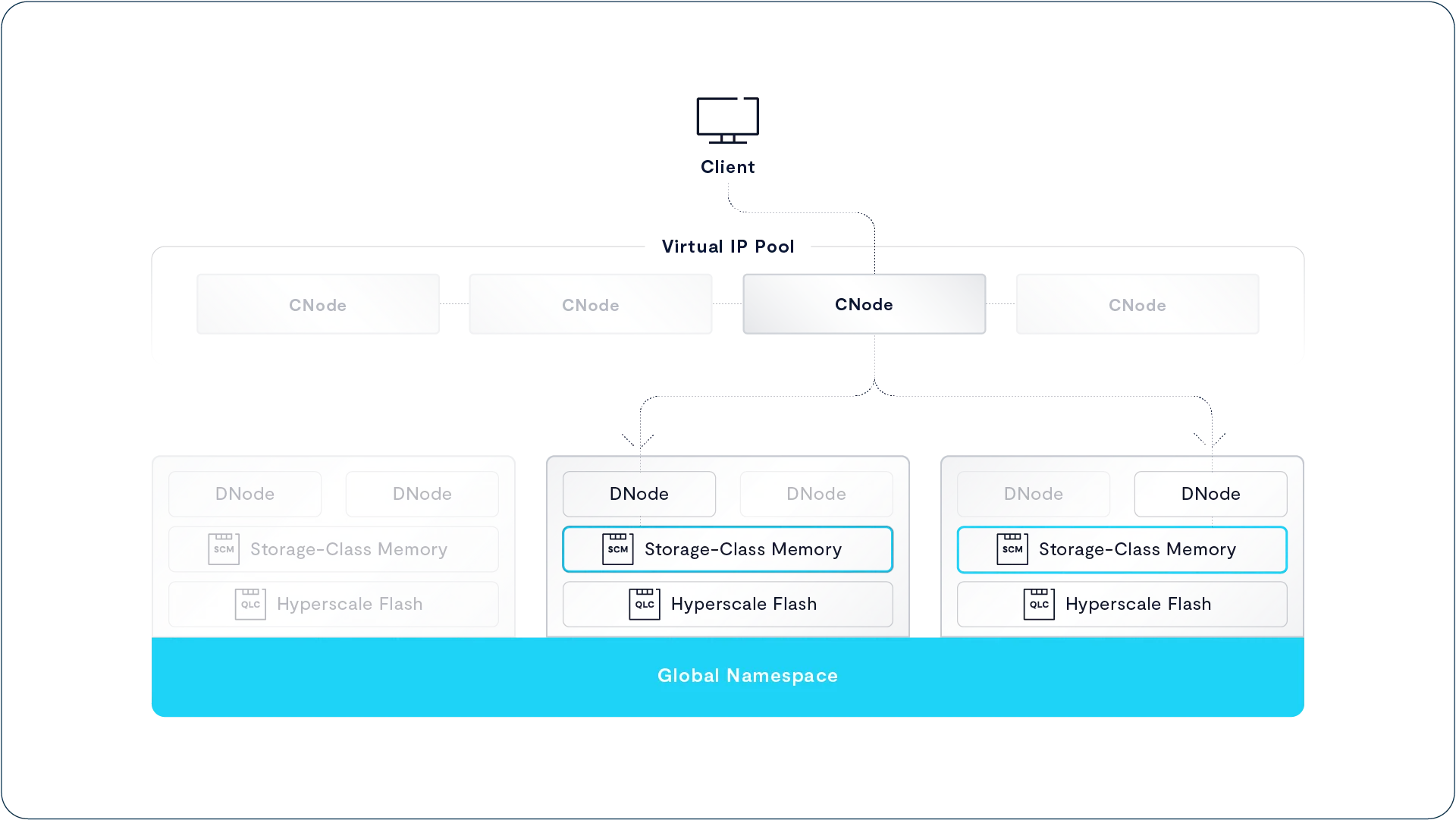
When a client writes data to an Element in the VAST DataStore, the CNode receiving that request writes the data to write buffers on two SCM SSDs. If encryption at rest is enabled, the data is encrypted by the CNode before being written.
Data is written to the write buffer in chunks that are generally the same size as the write I/O, though some large writes may be divided into multiple chunks
Once the data is written to both SSDs, the CNode updates the metadata for the write, which is also mirrored across two SCM SSDs and sends an acknowledgement to the client.
The system attempts to maximize the distance between the two copies of any data chunk or metadata block. Clusters with more than one DBox will write to SCM SSDs in different DBoxes. Clusters with only one DBox will write to SCM SSDs connected to the NVMe fabric through different DNodes.
Migrate to Flash

When the data in a cluster’s write buffer reaches a high water mark, the system starts the process of migrating data from the SCM to hyperscale flash. The migration process is distributed across multiple CNodes in parallel.
Each CNode reads data from the write buffer and reduces that data, which breaks the data into smaller variably-sized chunks that average somewhere between 16 and 64 KB. The CNode then writes that reduced data in very wide locally decodable erasure code stripes to the hyperscale SSDs.
This asynchronous migration provides inline data reduction while also having the time to reduce data more effectively. Since the migration process runs after writes are acknowledged to the client, data reduction time isn’t reflected in write latency. As long as CNodes in parallel can drain the write buffer faster than new data fills it, the time it takes to process any given data chunk is irrelevant.
Once an erasure code stripe has been written to the hyperscale SSDs, the CNode updates the system metadata to point to chunks in the new stripe and marks the write buffers it’s emptied as free for new data.
Write in Free Space Indirection
Conventional storage systems maintain static relationships between logical locations, like the 1 millionth-4 millionth bytes of Little_Shop_of_Horrors.MP4, and the physical storage locations that hold that data. As such, when an application writes to that location, the system physically overwrites the old data with the new in place. Back in the day of hard disk arrays, static mappings like this had the advantage of keeping sequential data physically adjacent, reducing the number of hard drive head motions.
DASE systems don’t have spinning disks; instead they use low-cost hyperscale flash SSDs to provide their capacity. It therefore doesn’t make any sense to optimize the data layout on a VAST cluster to maximize sequential I/O. Instead the VAST DataStore is optimized for the efficient use of both the capacity and the endurance of those SSDs.
The VAST DataStore uses a write-in-free-space data layout that performs all writes by way of indirection. New data is written to the hyperscale flash in full erasure code stripes as it’s migrated from the SCM write buffer. When data is logically overwritten, the metadata for the affected Element (file/object/table) is updated to point to the new data chunk.
The write-in-free-space method has several advantages:
Eliminates the read-modify-write overhead of overwrites in place
Provides pointer mechanisms for low-overhead snapshots, clones, deduplication, replication, and other services
Empowers the system to write and delete from SSDs in patterns to minimize flash wear
Challenges with Commodity Flash
The low cost of commodity, hyperscale-grade SSDs is an important part of how a VAST DataStore cluster can achieve archive economics. There are a few barriers that present challenges for legacy systems to use this new type of flash technology:
Write Performance: As the flash foundries squeeze more bits per flash cell, the resulting SSDs take longer to write data to the flash, as they carefully tune the charge in each cell to one of 16 (QLC) or 32 (PLC) voltage levels.
Endurance: Write endurance is the single biggest challenge when considering the use of commodity flash. Some Hyperscale flash drives can only be overwritten a few hundred times before they are worn out.
As we’ve already seen, the VAST DataStore uses SCM SSDs as a write buffer, and since VAST systems acknowledge writes once the data is safe on SCM SSDs, high write latency from the hyperscale SSDs doesn’t affect system performance. That same SSD write buffer also helps VAST systems manage endurance across the estate of hyperscale SSDs in the cluster.
Endurance Is Write Dependent
SSD vendors specify an SSD’s endurance in DWPD (Drive Writes Per Day for 5 years) or TBW (Terabytes Written) based on a JEDEC standard workload that includes 77% writes of 4 KB or smaller. This makes sense because many legacy storage products were designed to write in 4KB disk blocks and 4KB is how people tend to think about IOPS workloads – which is what people have been buying flash for in the first place.
The VAST DataStore was designed to run on the lowest-cost hyperscale SSDs, unlike more expensive enterprise SSDs, hyperscale SSDs write data directly to flash, without an internal DRAM buffer where the SSD controller can accumulate data and write it to flash in larger blocks. That’s significant because small writes to flash (<128 KB) consume significantly more of the SSD’s total endurance than the same data written as large I/Os.
As seen in the chart below, the endurance of the Intel P4326 SSD varies significantly based on the size and distribution of writes:
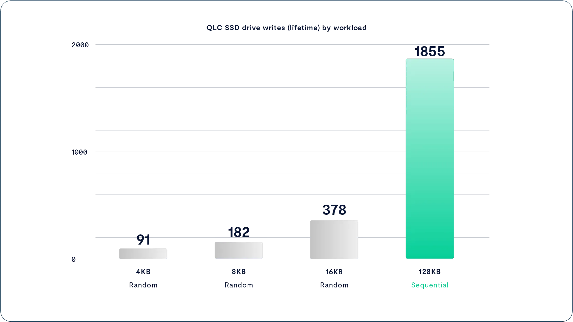
QLC SSDs provide 20 times more endurance when they’re written to in large sequential stripes as compared to being written to in the 4KB random writes, as is often common in many enterprise storage systems.
The reason hyperscale SSDs deliver higher endurance for large writes than small random writes is because those large writes better align with the internal structure of the flash in the SSD. Flash memory stores data in the form of a charge (some number of electrons) trapped within a memory cell.
The chip can then measure the charge in the cell, and based on the voltage of the charge in the cell decide what the value of the cell is. That’s easy with SLC flash: there’s either a charge (0) or not (1). With QLC flash the chip has to differentiate between 16 voltage levels to deliver 4 bits/cell.
The cells in a flash chip are organized in a complex hierarchy of structures, luckily only two of which are significant for managing flash:
The Page – The page is the smallest structure that can be written. Once any data is written to a page that data cannot be modified until the page is erased. Hyperscale SSDs today have pages 64-256 KB in size
The Erase Block – An erase block, which contains many (256-64K) pages, is the smallest unit the flash chip can erase. Erase blocks on today’s high-density flash are several MB in size
When the SSD controller receives new data, it writes that data to an empty page and updates the metadata of its internal log-structured data layout. Each write consumes one program/erase cycle of every cell in the page, so 4 KB writes consume a whole 128 KB page’s endurance.
When the SSD starts running out of space it has to garbage collect. It compacts the valid data from several erase blocks into new pages so those pages can be erased, to create more empty pages for the next batch of incoming data.
The problem is that erasing flash requires very high voltages, at least for the inside of a chip, and causes quantum dynamic wear on the flash cell insulation. Eventually this causes electrons to leak out and the flash cells can’t reliably hold data.
VAST Datastore Data Structures
Optimized for Hyperscale Flash
The VAST Datastore is designed to minimize write-amplification; that is the number of times any data is moved from one place to another, usually via garbage collection either in the write-in-free-space DataStore or internally to the SSDs.
The first step is a cluster-wide flash translation layer. The VAST DataStore manages the flash across all its hyperscale SSDs much like the SSD controller in an SSD manages its flash chips. In both cases the software takes advantage of special knowledge of the hardware’s abilities and limitations to manage those resources.
With Large Data Stripes, Drives Never Need to Garbage Collect
Legacy indirection-based file systems use a single logical block size through all their data services. Using fixed data sizes of 4 KB or 32 KB blocks for data reduction, data protection, and data storage keeps things simple for traditional storage systems, especially when sizing file system metadata stores because the systems can always point to a consistently-sized data block.
The problem with this approach is that it forces the storage architect to compromise between the low-latency and fine-granularity of deduplication of small blocks vs. the greater compressibility and lower flash wear of larger blocks. Rather than make that compromise, the VAST Element Store manages data at each stage of its journey:
Data is written to the SCM write buffer in the size of the write I/O to minimize latency
It is adaptively chunked into variable size chunks (average size 16-64KB) and reduced
Those data chunks are tightly packed into erasure code substripes each a multiple of the page size so the SSD controller can write full pages
Each erasure code stripe is made up of many sub-stripes, creating an erasure code stripe multiple times the size of the SSD’s erase block
The VAST DataStore writes to SSDs in 1 MB I/Os, a significant multiple of the underlying flash’s 64 KB-128 KB page size, thereby allowing the SSD controller to parallelize the I/O across the flash chips within an SSD. It also completely fills flash pages, preventing the write amplification that is caused by partially written pages.
The Element Store manages data in deep data strips that layer 1 MB I/Os into a larger 1 GB strip of data on each SSD. Just as writing 1 MB I/Os to the SSDs aligns the write to a number of full flash pages, managing data in 1 GB strips aligns each erasure code stripe with a set of erase blocks inside the SSD.
When the VAST DataStore performs garbage collection, it erases the entire 1 GB erasure code strip from each SSD, causing the SSD controller to erase the entire contents of several erase blocks. This leaves no data for the SSD controller to relocate and therefore prevents the SSD from having to perform internal garbage collections.
The 1 GB strip depth and 1 MB sub-strip depth are not fundamentally fixed values in the VAST DataStore architecture but were determined empirically by measuring the wear caused by writing and erasing multiple patterns on today’s generation of capacity SSDs. As new SSDs are qualified and as PLC flash enters the market, the VAST Cluster write layout can adjust to even the larger writes and erases future generations of flash will require to minimize wear.
The underlying architecture components make all of this intelligent placement possible:
A large, distributed buffer, built from SCM, provides the system with the time needed to form a collection of erasure-encoded write stripes as large as 146+4 – giving the application snappy response times without the need to hold up writes before flushing data down to hyperscale flash
NVMe-oF and NVMe drives provide the shared-everything cluster foundation that makes it possible for multiple writers to gracefully fill erase blocks with 1 MB strips
VAST Foresight
Retention-Aware Data Protection Stripes
The one big downside to a write-in-free-space data layout is that eventually the system runs out of free space, and the system has to garbage collect, relocating the still-valid data chunks mixed in with all the deleted and overwritten data ready for the proverbial bit bucket. Foresight minimizes the write amplification created by this garbage collection by writing data to erasure code stripes based on the data’s life expectancy.
Before Foresight, storage systems generally wrote data to their drives in the order the data was written to the system. If one set of hosts creates the final render of “Sherlock Holmes vs Dracula” while another set of hosts writes thousands of temp files for another project, the data from those two streams is going to be interleaved as it’s written.
If that storage system used a log-structure or other write-in-free-space layout it would have to garbage collect and compact the render data some time after the temp files are deleted. Over three or four years data that hasn’t been logically moved may still be relocated by garbage collection several times, consuming valuable flash wear each time.
Rather than storing data in the order it was written, or with logically adjacent data physically adjacent to optimize sequential reads for hard disks, Foresight organizes data into erasure code stripes based on its life expectancy. The metadata describing each chunk in the VAST DataStore’s physical layer has a life expectancy value.
When the system builds erasure code stripes it assembles data chunks with similar longevity. The temporary files and final render data will get written to different erasure code stripes. Once the temporary files are deleted those erasure stripes will be mostly empty, leaving little data to move during garbage collection.
VAST DataStore only garbage collects when free space falls below a low water mark, and garbage collects from the erasure code stripes with the most recoverable space which, combined with Foresight, allows the garbage collection process to create the most free space with the least data motion.
The data that is garbage collected has its life expectancy increased. Over time, this will cause the very long-lived data on the system to accumulate into erasure code stripes for “immortal” data stripes where they can live permanently eliminating the repeated relocation of garbage collection on legacy systems.
Endurance Is Amortized
Wear-Leveling Across Many-Petabyte Storage
The VAST DataStore also extends flash endurance by treating the petabytes of flash in a cluster as a single pool of erase blocks that can be globally managed by any VAST Server. The VAST Cluster performs wear-leveling across that pool to allow a VAST DataStore system to amortize even very-high-churn applications across petabytes of flash in the Cluster. Because of its scale-out design, the VAST Cluster only needs to work toward the weighted overwrite average of the applications in an environment, where (for example) a database that continually writes 4 KB updates will only overwrite a fraction of even the smallest VAST cluster in a day.
The large scale of VAST clusters is also key to the system’s being able to perform garbage collection using the 150 GB stripes that minimize flash wear and data protection overhead. Unlike some other write-in-free-space storage systems, the VAST Element store continues to provide full performance up to 90% full.
A Breakthrough Approach to Data Reduction
The long history of data reduction has primarily been concerned with the refinement of compression and deduplication: two complementary techniques that use computing power to reduce the size of data stored. Compression, the older technique, reduces repeated copies of small bit patterns over a limited range. Deduplication techniques eliminate repeated patterns in much larger blocks over correspondingly larger sets of data.
The VAST DataStore uses these two techniques and also adds a new technique called similarity reduction. This reduces the amount of storage needed to store data chunks that are similar, but not identical, to existing chunks. We are so confident the VAST DataStore will reduce any unencrypted dataset better than any commercially available storage solution that we guarantee it.
This section provides a high-level view of VAST’s data reduction methods, including similarity reduction. For a deeper dive see “All Data Reduction Is Not Equal.”
Beyond Deduplication and Compression
Traditional compression operates over the limited scope of a block of data or a file of a few KB to a few MB. The compressor identifies small sets of repeating data patterns, such as the nulls padding out database fields or frequently used words. It replaces those repeating patterns with smaller symbols and creates a dictionary defining what data that symbol represents. To decompress the data when a read is issued, the data-to-symbol dictionary is used to reverse the process and replace the symbols with the corresponding, larger data strings.
Many file types, especially for media, include compression as part of the file type definition. Since these compression techniques can be specific to the type of media being stored, like H.264 MPEG storing frames as the changed pixels since the last frame, they can be more effective than more generic storage system compression algorithms. As a result, some unstructured data repositories may not see any significant compression from the storage system.
Data deduplication, by comparison, identifies much larger blocks of data that repeat globally across a storage namespace. Rather than storing multiple copies of the data, a deduplication system uses pointers to direct applications to a single physical instance of a deduplication block. Most deduplication systems break data into chunks somewhere between 4KB and 1MB in size. It then hashes the chunks and looks for duplicates. It saves duplicate chunks 2–n as pointers to the original chunk.
Because deduplicated data stores are based on pointers, deduplicating systems have to rehydrate data for sequential reads, making random read I/Os on the backend to reassemble data that’s logically sequential but stored randomly across the deduplicated repository. This makes deduplicating storage systems that use hard disks on the back end much slower for reads as the hard drives thrash their positioners. SSDs perform random and sequential I/O at equal speeds, eliminating this rehydration tax.
The block hashing employed by deduplication is much more sensitive to very small differences in data and therefore can force a deduplication system to store a new, full block of data even when there is just a single byte of difference between deduplication blocks. This has the effect of doing a lot of work to hash the blocks without substantial dataset size reduction.
To minimize this sensitivity to entropy in data, deduplication systems can deduplicate with smaller block sizes. Small deduplication blocks create more metadata, and since most deduplicating systems have to hold the table of hashes already stored in DRAM, deduping on smaller blocks requires more memory and more CPU to manage the memory, and may not pay off in lower system cost.
Similarity Reduction to the Rescue
The combination of hyperscale flash, ten years of system longevity, and breakthrough erasure code efficiency creates an economically compelling proposition for organizations that are looking to reduce the cost of all-flash or hybrid (flash+HDD) infrastructure. The VAST approach to global data reduction, known as similarity-based reduction, further redefines the economic equation of flash. It is now possible to build a system that provides a total-effective-capacity acquisition cost that rivals or betters the economics of an all-HDD infrastructure. The objective is simple: to combine the global benefits of deduplication-based approaches to data reduction with the byte-granular approach to pattern matching, which until now has only otherwise been found in localized file or block compression.
A flash system can cut up and correlate data for purposes of data reduction that results in a block size on disk that is extremely small, turning every workload into an IOPS workload. When one has a system that has, for all purposes, unlimited IOPS, this becomes an ideal workload. This same workload on HDDs would result in tremendous fragmentation and HDDs simply can’t deliver enough IOPS to support the many random-access reads in fine-grained data reduction. It may seem counter-intuitive, but the only way to build a system that can beat the economics of an HDD-based storage system is using similarity-based reduction with commodity flash.
Similarity Reduction
When data is written to the VAST DataStore, it is first written to the storage-class memory (SCM) write buffer and acknowledged (ACKed). The VAST DataStore then performs data reduction as part of the process of migrating data from the SCM write buffer to the hyperscale flash capacity pool.
Since writes are acknowledged to applications when written to the SCM write buffer, VAST systems have plenty of time to perform more meticulous data reduction. As long as the system drains the write buffer as fast as new data is written to the system, the time it takes to reduce the data has no impact on system performance or write latency.
Adaptive Chunking
The VAST systems break data into variable-size chunks (average size between 16 and 64 KB) using a rolling hash function to maximize storage efficiency. It then hashes the chunks with several hash functions, including a strong hash to give the chunk a unique identity. As with conventional deduplication, when multiple chunks of identical data are written, the system stores a single copy of the data and uses metadata pointers for the rest.
The system also hashes the chunk with a series of similarity hash functions. The strong hashes used for deduplication are designed to be collision resistant; a small change in the input data causes a large change in the output so two different blocks of data don’t generate the same hash. Similarity hashes are, by comparison, weak hashes; they’re designed to generate the same hash value for any inputs that are within a short cryptographic distance of each other. In plain English that means these similarity hash functions will generate the same hash for any chunks that require a small number of bits to be flipped to turn one chunk into another.
If it will only take a few bit flips to turn chunk A into Chunk B that means there must be multiple, significant strings of byte that are the same across the two chunks. That in turn means that the two chunks will compress with the same compression dictionary to reduce those strings to symbols.
When a chunk of new data generates a unique similarity hash, that chunk is compressed with ZSTD, a new compression algorithm from Facebook optimized for decompression performance, and added to the erasure-code stripe the current CNode is assembling. When a chunk of new data generates a similarity hash that’s the same as the hash generated by a previous data chunk, the system recalls the original reference chunk and compresses the new data with the compression dictionary from the reference chunk. The system then stores the resulting compressed data as a delta block without the overhead of storing the dictionary a second time.
A Single Reduction Realm
As we noted earlier, conventional deduplication systems have to store their hash tables in DRAM to process data fast enough. This limits the amount of data they can deduplicate to the amount of memory a single controller can hold, about 1 PB for the largest purpose-built backup appliances. Once a dataset grows to the point where it has to be spread across multiple appliances, each appliance forms an independent deduplication realm and any data chunks that are written to multiple appliances will be stored multiple times. Some systems limit the effectiveness of their deduplication by deduplicating within volumes, file systems, or other intermediate abstractions. This creates even more deduplication realms, and copies of really common data.
Scale-out systems face the even more challenging problem of maintaining a hash table in memory across a cluster without generating so much east-west traffic between the nodes that deduplication is no longer practical. The result is that deduplication is less common on scale-out systems and requires compromises such as having a local hash table in each node, effectively turning each node into a separate deduplication realm.
VAST systems store their hash tables and other DataStore metadata on SCM SSDs in HA DBoxes. Because those SCM SSDs are shared across all the CNodes, the entire cluster constitutes a single data reduction realm for deduplication and similarity, and since there’s SCM in every DBox that gets added to the cluster, that single reduction realm can grow to exabytes.
Similarity Reduction in Practice
The efficiency that can be gained from similarity-based data reduction is of course data-dependent. While encrypted data will see almost no benefit from this approach (or any other form of data reduction), other applications will often see significant gains. Reduction gains are, of course, relative—and where a VAST cluster may be 2x more efficient than a legacy deduplication appliance for backup data (at 15:1 reduction), a reduction of 2:1 may be as valuable in an unstructured data environment where legacy file storage systems have not ever been able to demonstrate any reduction.
Some examples of VAST’s similarity reduction, derived from customer testing, include:
AI/Machine learning training data: 3:1
Enterprise backup files: up to 20:1
Log stores (indexes and compressed data): 4:1
Multi-tenant HPC environments: 2:1
Pre-compressed (GZIP) financial services market data: 1.5:1
Pre-compressed video: 1.1:1
Seismic data: 3:1
VFX and animation data: 3:1
Weather data: 2.5:1
A deeper dive into VAST’s similarity-based data reduction is found in “All Data Reduction Is Not Equal.”
A Breakthrough Approach to Data Protection
Protecting user data is the primary purpose of any enterprise storage system. However, conventional data protection solutions like replication, RAID, and Reed-Solomon erasure coding force difficult trade-offs between performance, resiliency, storage overhead, and complexity. To address these issues, the VAST DataStore combines Storage Class Memory (SCM) and NVMe-over-fabrics (NVMe-oF) with innovative erasure codes to deliver high resiliency and performance with unprecedented low overhead and low complexity.
One of the primary design tenets of the VAST cluster architecture was to bring the system overhead down from 200% (using an acute-case example, triplication overhead) to as little as 3% while also increasing the resilience of a cluster beyond what classic triplication and erasure codes provide today. The result is a new class of error-correction codes that deliver higher resiliency (millions of hours mean time to data loss) and lower overhead (typically under 3%).
This section describes how VAST systems protect data at a high level. For a deeper dive see “Ensuring Storage Reliability at Scale.”
Wide Stripes for Storage Efficiency
The key to efficiency in data protection is to write wide erasure code stripes. It’s obvious that an erasure code that writes 8 data strips and 2 parity strips per stripe, abbreviated 8D+2P, has more overhead (20%) than a 14D+2P stripe would (12.5%).
Since a single failure in a shared-nothing node will take all the drives in that node offline, shared-nothing systems have to treat the node as a unit of failure, striping across nodes as well as drives. Because the DASE architecture uses highly available storage enclosures (DBoxes), VAST systems can stripe across all the hyperscale SSDs in a cluster, safe in the knowledge that no single failure will take more than one SSD offline.
Because there are many more SSDs than enclosures, this means DASE clusters can write erasure code stripes much wider, up to 150 total strips per stripe. This achieves much lower overhead than a shared-nothing architecture, where a node is a unit of failure. For example:
A small collection of VAST just a bunch of flash (JBOFs) can provide redundant access to a collection of drives striped across the enclosure in a 146+4 SSD write stripe
If a shared-nothing cluster were to implement this same stripe width, a system would require nearly 40 storage servers to achieve this same level of low overhead
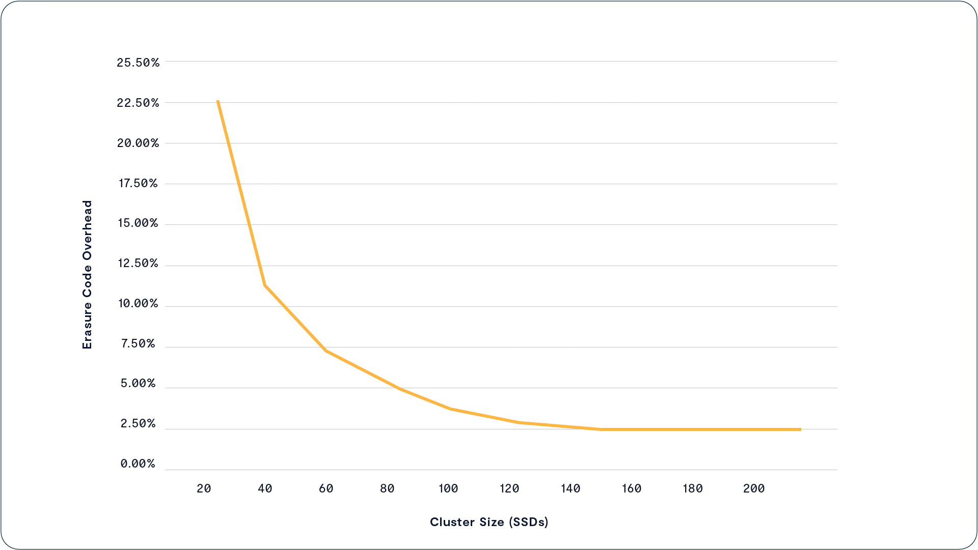
Quad Parity for Higher Resilience
Wide write stripes are the means to maximize storage efficiency, but wide stripes also increase the probability that multiple devices within a stripe could fail. While flash SSDs are very reliable devices, especially when compared to HDDs, it’s simply more statistically likely that two of the 148 SSDs in a 146+2 stripes will fail, than 2 stripes out of the 12 SSDs in a stripe coded 10+2.
To support wide stripes and the resilience to provide the 11 9s of data durability that exabyte data repositories demand, VAST systems always write erasure-code stripes with four parity strips. This allows a VAST system to rebuild its data protection, and continue to serve data to users, with as many as four simultaneous SSD failures.
While adding additional parity strips to a write stripe helps increase the stripe’s resilience, this is not enough to counterbalance the higher probability of failure that results from large write striping. The other aspect of ensuring high resilience in a wide-write-striping cluster is to minimize the time to recovery.
VAST Data Locally Decodable Codes
Storage systems have historically kept erasure-coded stripe sizes narrow. That’s because the RAID and Reed-Solomon erasure codes they use require systems to read all the surviving data strips in a protection stripe, and one or more parity strips, to regenerate data from a failed drive.
To understand this problem in practice, consider a storage system using the same distribution of 146 data strips and four (4) parity strips per erasure-code stripe (146D+4P) as a large VAST Cluster with Reed-Solomon erasure codes. When an SSD on that system fails, the system has to read the contents of all the surviving data SSDs plus one of the four parity strips, for a total of 146X the failed SSD size.
To avoid rebuilds of that magnitude, which would consume a large fraction of our hypothetical system’s performance for days or weeks, storage vendors limit the blast radius of device failures by keeping erasure code stripes below 16 - 24 total data and parity strips per stripe.
To get around this problem, VAST Data designed a new class of erasure code borrowing from a new algorithmic concept called locally decodable codes. The advantage of locally decodable codes is that they can reconstruct, or decode, data from a fraction of the surviving data strips within a protection stripe. That fraction is proportionate to the number of parity strips in a stripe. A VAST cluster reconstructing a 146D+4P data stripe only has to read 38 x 1-data strips, just ¼th of the survivors.
How Locally Decodable Erasure Codes Work
VAST’s locally decodable codes calculate each protection strip from slightly different sets of data strips across more than just one stripe of data. This allows protection strips to “stand-in” for large groups of data strips during rebuild calculations. By having three parity strips “stand-in” for ¾ of a stripe’s data strips, the system only needs to read from 1/4th of the surviving data strips in a rebuild to perform a recovery within a stripe.
Storage-Class Memory Eliminates the Need for Nerd Knobs
Too many storage systems present administrators with a dizzying assortment of stripe widths and RAID protection levels. The VAST DataStore can maintain a fixed selection of n+4 data protection because the very large SCM write buffer in a VAST system decouples write latency from the backend locally decodable stripe layout. In other words, it reduces latency by acknowledging writes once they are stored in the SCM and it can handle the encoding process asynchronously.
Writes to SCM are mirrored. The low latency of SCM combines with the fact that, unlike flash, SCM devices don’t have a logical block addressing (LBA), page, block hierarchy, or complications that hierarchy creates. Their prodigious endurance isn’t dependent on write patterns the way flash SSDs are. This means the SCM write buffer provides consistently high write performance regardless of the mix of I/O sizes. Any data written by an application is written immediately to multiple SCM SSDs. Once data is safely written to the SCM, the write is acknowledged to the application. Data is migrated to hyperscale flash later, after the write has been acknowledged.
On the flip side, the random access of flash combines with VAST’s wide write stripes and parity declustering to ensure that reads are very fast because all writes are parallelized across many flash devices. That said, locally decodable erasure codes do not require a full-stripe read on every operation. To the contrary, reads can be as little as one SSD chunk and as large as a multitude of stripes. In this way, there is only a loose correlation between the width of a stripe and the width of a file, object, directory, or bucket read.
Intelligent, Data-Only Rebuilds
The VAST DataStore knows which blocks on each SSD are used for active data, which are empty, and which are used but are holding deleted data. When an SSD fails, we only have to copy the active data and can ignore the deleted data and empty space.
Declustered Parity
Rather than clustering SSDs to hold data strips, parity strips, or spares, the VAST DataStore distributes erasure-coded stripes across all the SSDs in the system. The system selects which SSDs to write each stripe of data, based on SSD space and wear, not the locations being written. Data is then layered into the 1 GB strips via a collection of sub-stripes. which can each be written by different VAST Servers.
Because of the shared-everything nature of the DASE architecture, recovery processes are sharded across all the VAST servers in the cluster. VAST’s declustered approach to data protection ensures that every device has some amount of data and parity from an arbitrary collection of stripes. This makes it possible to federate a reconstruction event across all of the available SSDs and all of the VAST server resources in a cluster. A large VAST DataStore System will have dozens of VAST Servers sharing the load and shortening rebuild time.
A Fail-in-Place Cluster
As storage systems scale to hundreds of SSDs, failures are inevitable. VAST systems are designed to allow SSDs to fail in place. Rebuilds in large clusters are not dependent on failed devices being replaced, even if multiple SSDs fail. VAST systems always write erasure code stripes somewhat narrower than the total number of SSDs in the system so there’s space to rebuild into.
Large VAST clusters, those with more than 160 total hyperscale SSDs, can repair from multiple drive failures by writing to free space on drives that didn’t participate in any erasure code stripe. Smaller clusters will write narrower erasure code stripes. Either way, the system will continue to operate, and maintain protection against four additional SSD failures as long as there’s enough free space to do so.
VAST Checksums
To protect user data from the silent data corruption that can occur within SSDs, the VAST DataStore keeps a checksum for each data and metadata chunk in the system. These checksums are CRCs calculated from the data chunk or metadata structure’s contents and are stored in the metadata structure that describes the data chunk. The checksum for a folder’s contents is stored as part of its parent folder, the checksum for a file extent’s contents in the extent’s metadata, and so on.
When data is read, the checksum is recalculated from the data chunk and compared to the checksum in the metadata. If the two values are not the same, the system will rebuild the bad data chunk using locally decodable parity data.
However, solutions that store checksums in the same block (or chunk) as the data, such as ANSI T10 Data Integrity Field standard (T10-DIF), only protect data from SSD bit rot, but they do not protect the data path from internal system data transfer errors. If, in the case of T10-DIF, there is as little as a 1-bit error when transmitting an LBA address from an SSD, and the SSD actually reads LBA 33,458, a T10-based system will return the wrong data, because it’s reading the wrong LBA, but the data and checksum will match because they’re both from LBA 33,458 even though we wanted the data from 33,547.
To protect data being stored on the system from experiencing an accumulation of bit errors, a background process also scrubs the entire contents of the system periodically. Unlike the CRCs that are attached to VAST’s variable-length data chunks, the system creates a second set of CRCs for 1 MB flash sub-strips in order to swiftly perform background scrubs. This second level of CRCs solves the problem of customers who store millions, or billions, of 1-byte files; VAST’s background scrubber can deliver consistent performance irrespective of file/object size.
Rack Scale Resilience via Enclosure HA
While the VAST architecture is highly resilient with no single point of failure, any single appliance remains vulnerable to failures of power or network service to the rack they’re housed in. Larger VAST systems can remain available even through the loss of a full enclosure by adopting the HA option.
A VAST system with 15 enclosures will use erasure code stripes of 146+4 with 2.7% overhead, but since each enclosure holds more strips of each erasure code stripe than the four losses the system can correct for, the system will go offline if any of the 15 enclosures goes offline.
VAST clusters with HA use narrower erasure code stripes than VAST systems normally do–writing only two strips of each erasure code stripe to each enclosure. A 15-enclosure system will now write stripes with 22 data strips and 4 parity strips, raising the protection overhead to 15.4%. Because a failure only removes 2 strips from each stripe, and the locally decodable codes can reconstruct data from as many as four erasures, the system can run right through a failure and continue to serve data.
Encryption at Rest
Encryption at rest is a system-wide option. When enabled, VAST systems encrypt all data using FIPS 140-3 validated libraries as it is written to the Storage Class Memory (SCM) and hyperscale SSDs.
Even though Intel’s AES-NI accelerates AES processing in microcode, encryption and decryption still require a significant amount of CPU horsepower. Conventional storage architectures, like one scale-out file system that always has 15 SSDs per node, can only scale capacity and compute power together. This leaves them without enough CPU power to both encrypt data and deliver their rated performance.
Conventional storage vendors resolve this by using self-encrypting SSDs. Self-Encrypting Drives (SEDs) offload the encryption from the storage controller’s CPU to the SSD controller’s CPU, but that offload literally comes at a price; that is, the premium price SSD vendors charge for enterprise SEDs.
To ensure that we can always use the lowest-cost SSDs available, VAST systems encrypt data on the hyperscale SSDs in software, avoiding the cost premium and limited selection of self-encrypting SSDs. VAST’s DASE architecture allows users to simply add more computing power, in the form of additional VAST Servers, to accommodate the additional compute load encryption may present.
Rather than being a performance limitation, or significant additional cost, VAST encryption becomes just one more factor in balancing the performance provided by VAST Server CPUs and the capacity of VAST enclosures.
The Logical Element Store Layer–Building Elements from Data Chunks
As we’ve seen, the Physical Layer takes a revolutionary new approach to the device management and data protection functions traditionally performed by logical volume managers, RAID controllers, and SAN arrays, delivering unprecedented scale and efficiency. By that same measure, the VAST Element Store is an Uber-namespace generalized and abstracted to store structured as well as unstructured data.
It’s important to note that the physical and logical layers of the VAST DataStore are much more tightly integrated than our comparison to a logical volume manager and file system/object namespace would imply. In those legacy architectures the RAID system presents virtual volumes and the file system can only address the media by Logical Block Addresses (LBAs) on those virtual disks.
The Element Store Layer’s metadata provides the structure that organizes the data chunks stored in the Physical Layer into Elements of several types. Because the Element metadata is managing logical chunks, not just blocks on a virtual disk, the Element layer and chunk layer are much more tightly integrated than a volume manager and file system.
Each Element is defined by its metadata and the methods/protocols used to access it. Since the goal of the VAST DataStore is to provide universal storage with universal access so users can access all their data via whatever protocol is convenient for them at the time. The Element Store maintains an abstract set of metadata properties about each Element that includes metadata properties required by any access protocol.
This allows VAST system operators to apply S3 metadata tags to Elements that are never actually accessed as S3 objects, like database tables and NVMe over Fabrics volumes. A university could tag such Elements with ownership information and then, for example, quickly query The VAST Catalog to find all of Dr. Doofenshmirtz’ data when he left the university due to his imprisonment.
The VAST Element Store manages three types of data elements:
File/object - File/object Elements are stored by the system as strings of data chunks
File/object Elements are accessed through the NFS, SMB, and S3 protocols
Volume - Volume Elements, like file/object Elements, are stored as strings of data chunks. Volume Elements have additional access control lists and authentication metadata.
Volume elements are accessed via NVMe/TCP, the modern block protocol.
Table - Table Elements hold structured, tabular data in a columnar format
Table Elements are accessed via SQL
We’ve long talked about files and objects as being unstructured data while database management systems held structured data. To the VAST Element Store, unstructured means that the Element's contents are opaque to the VAST Data Platform. The system can reduce and fingerprint the data, but if customers want to glean insight from the contents of those Elements, it will have to come from outside the system. Structured data, therefore, means that data where the system understands the internal structure of the Element and can access the contents to glean insight.
Inherently Scalable Namespace
Users have long struggled with the scaling limitations of conventional file systems for a variety of reasons, such as metadata slowdowns when accessing folders that contain more than a few thousand files. Other systems deal with challenges around having preallocated inodes that limit the number of files that can be stored in a filesystem as a whole. These limitations were one of the major drivers behind the rise of object storage systems in the early 2000s. Freed from the limitations of storing metadata in inodes and nested text files, object stores scale to billions of files over petabytes of data without being bogged down.
The VAST DataStore provides the essentially unlimited scalability promised by object stores for applications using both object and file access methods and APIs. The DataStore’s V-Trees expand as enclosures are added to the VAST cluster, with consistent hashes managing the distribution of V-Trees across enclosures (all without explicit limits on object sizes, counts or distribution).
Discovering a New Element – The Table
We’ve always called the namespace a VAST Cluster creates and presents as an Element Store because The VAST Element Store can accommodate the hierarchical structures of file systems and the flat organization of object buckets, using the word Element to mean a file or an object and. While files and objects are accessed by different protocols, they are both opaque containers, with the VAST system ignorant of their internal structures.
The VAST DataStore uses B-Tree structures to build File/Object type Elements as a simple list of the data chunks we described in the physical layer section. Elements that hold tables are different because the VAST Data Platform is aware of their internal structure. The metadata for Table type Elements still maps the table’s contents to physical layer data chunks. Where the metadata for a File/Object Element sequentially maps byte offsets within the file to data chunks, the metadata for Table Elements maps the table’s contents by row and column to those data chunks.
Because that metadata is stored in shared non-volatile memory in VAST DBoxes, it’s available to, and shared by, all the CNodes in the VAST cluster. There’s no metadata server to become a bottleneck or metadata cluster to manage, allowing a single VAST cluster to scale to exabytes. It also allows the VAST DataStore to be fully ACID so it can support the transaction consistency applications expect from relational databases as well as the query performance required to suggest a hotel, or movie, you would like in seconds.
To be more specific, the VAST DataStore stores tables into reduced data chunks with a columnar structure that is similar to the way Parquet files are organized but at a much finer granularity. Each data chunk holds the values of one or more columns for a row group in the table. Some of the statistics about those column values are stored in the table’s metadata as well as the chunk footer to accelerate queries.
Because data is stored in its natural form as a table by the VAST DataStore, users are relieved of the tasks of partitioning their tables across files of the right size to maximize the large sequential reads that disk-based object stores are good at. Perhaps paradoxically combining the storage and data layout functions into a single VAST DataStore relieves data scientists from having to plan table layouts to accommodate storage limitations.
If the data was in Parquet files in an S3 data lake with the recommended row group size of 128MB to 1GB in size, then Spark, Trino, or some other query engine would have to read the footer from all the Parquet files in the bucket, then read an average of 512MB of data for each row group that isn’t disqualified from the query because, for example, the min in the footer is greater than the range being queried.
The VAST DataBase can perform the whole footer scanning stage by reading from the metadata store alone, without reading any data chunks and since the data chunks are small (4,000x smaller than a standard Parquet row group according to Apache Iceberg best practices) will have to read much less data for each row group identified as having data of interest from footer data. Since the VAST footer is logical, it could also be extensible allowing customers to add additional statistics to the footers to accelerate their common queries.
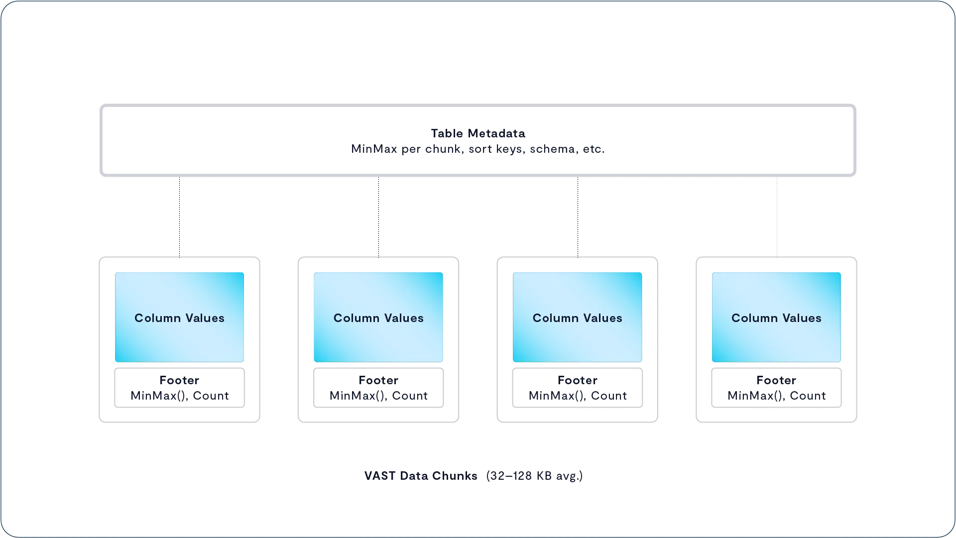
This treatment of tables as a special class of Element is just one aspect of the unique level of integration within the VAST Data Platform. Previous data management platforms were built using discrete components. In those systems structured data meant that database management engine imposed structure on the data in the files it created but none of that structure carried through down to the file system.
The VAST Data Platform uniquely uses one set of integrated metadata to manage data from a specific field in a table through the Element of the table itself to a particular data chunk and ultimately to a location on an SSD. In this section we’ve explored how tables are stored, we’ll examine how the VAST Data Platform manages tables, and the services it provides for tables in the section on The VAST DataBase.
Even though we’ve broken up the conversation here to make it easier to understand and provide simple comparisons to the traditional data platforms it’s important to remember that the VAST Data Platform is one integrated whole managing data from field/cell to SSD and beyond..
Element Store Data Services
Legacy storage systems have traditionally provided data services like snapshots and replication at the volume or file system level. This forces users to create multiple file systems to provide different service levels to their datasets.
The VAST DataStore creates a single namespace that eliminates the need for users to manage intermediate abstractions such as volumes and file systems. Instead, the VAST DataStore provides snapshots, replication, and similar services for any folder/bucket in the VAST Element store.
Low-Overhead Snapshots and Clones
A write-in-free-space storage architecture is especially suitable for high-performance snapshots because all writes are tracked as part of a global counter and the system can easily maintain new and old/invalid state at the same time. VAST brings this new architecture to make snapshots painless, by eliminating the data and/or metadata copying that often occurs with legacy snapshot approaches.
The VAST Element Store was designed to avoid several of the mistakes of previous snapshot approaches and provides many advantages for VAST DataStore users.
VAST Snapshots leverage zero-copy mechanisms for both data and metadata to minimize the bad performance effects of storing and deleting snapshots
VAST Snapshots do not require snapshot space/reserves. Snapshots use any free space and provide greater flexibility of media utilization as compared to more rigid approaches
VAST Clusters experience negligible performance impact when they have an arbitrary number of snapshots active
Instead of making clones of a volume’s metadata every time a snapshot is created, VAST snapshot technology is built deep into the metadata data structure itself. Every metadata object in the VAST Element Store is time-stamped with what is called snaptime. The snaptime is a global system counter that dates back to the installation of a VAST cluster and is advanced synchronously across all the VAST Servers in a cluster approximately once a minute.
As with data, metadata in the VAST Element Store is never directly overwritten. When an application overwrites a file or object, the new data is written in free space across the SCM write buffer. The system creates a pointer to the physical location of the data and links that pointer into the V-Tree metadata that defined the object.
Following VAST’s general philosophy of efficiency, VAST snapshots and clones are based on the small (average size 16-64 KB) data chunks that are the backbone of the VAST DataStore’s physical layer. That’s significantly finer grained than those on many conventional storage systems which may snapshot on pages of 1 MB or larger.
When you create a snapshot in the VAST Element Store, the system preserves the most recent version of the metadata pointers within the protected path, along with the data chunks that metadata references until the snapshot is deleted. The snapshot presents the data using the metadata pointers with the latest snaptimes earlier than the snapshot’s time.
Because VAST snapshots are based on snaptimes, all snapshots taken at the same time are consistent across a VAST cluster. There’s no need to define consistency groups; just use a single protection policy for all the paths you need to take consistent snapshots across.
When the system performs garbage collection it will delete the metadata pointers that aren’t either the latest version of that pointer or used by a snapshot, and any data used exclusively by those pointers.
Users can, of course, create snapshots on demand with a call to the system’s REST API, or through the GUI which will call the REST API itself, but most snapshots are managed through protection policies.
Once a protection policy is established the VAST DataStore presents a ./snapshots system folder in the root folder of each protected path. The ./snapshots folder will contain a subdirectory for each snapshot that provides read-only access to the snapshot’s contents. Several VAST customers use the ./snapshot feature to provide self-service restores to their users.
Truly Independent Clones
VAST clones provide rapid read-write access to a snapshot’s contents by creating an independent replica of a snapshot’s contents. When a VAST administrator creates a clone of a snapshot through the RESTful API, the system performs a background server-side copy of the snapshot’s contents to the specified directory.
The new folder and its contents appear and are available for both reads and writes in seconds. While the cloning process is in progress, read requests for data from the clone will be satisfied from the snapshot. Since the VAST DataStore only keeps a single copy of any data chunk, these copies occupy no space in the DataStore. This process can also be used to create clones of snapshots on a remote VAST cluster. See Global Clones below for details.
Administrators can choose to perform a full background copy of the snapshot’s contents or to allow the system to be lazy and only copy data to the clone as it is accessed. Lazy clones minimize the amount of data copied, and therefore the impact on the system, making them perfect for when you have to mount multiple clones to locate the last known good point in time.
Once the background copy is complete, the new folder has a metadata structure that is completely independent (other than the fact that both sets of metadata point to the same data chunks in the VAST DataStore’s physical layer). When a user clones their Windows Server golden image after every patch Tuesday there’s no complex dependency web amongst those clones of clones of clones of clones.
Indestructible Storage Protects from Ransomware and More
Users today face a plethora of ever more sophisticated attacks on their sensitive data. Snapshots provide protection against ordinary users encrypting or deleting data. Today’s ransomware attacks are more sophisticated, acquiring administrator/root/uberuser privileges and deleting or encrypting snapshots and backups as, or before, they attack the user’s primary data.
VAST’s Indestructible Snapshots protect against these sophisticated attacks and any other attacks that depend on elevated privileges, such as disgruntled administrators turning rouge, by preventing anyone, regardless of their administrative privileges on the system, from deleting Indestructible Snapshots before their expiration date.
To create Indestructible Snapshots users simply select the Indestructible option when creating the snapshot. There are three options to do this: through the GUI, through the REST API in the script that runs at the end of a backup job, or in the Protection Policy. Once an Indestructible Snapshot is created, that snapshot is immutable—no user, not even the proverbial root user, can delete the snapshot or modify the policy.
While truly indestructible snapshots that no one could ever delete sound appealing to corporate CISOs, in the real world, there may be situations where customers need to delete snapshots they’ve marked as Indestructible or run out of space. In those cases, VAST support can provide a time-limited token to the user that will temporarily enable deleting Indestructible Snapshots.
Support will only release a time-limited token to a pre-authorized customer representative after meeting the conditions set in advance by that customer. Customers may require that three of seven designated people make the request, that a secret pass phrase be spoken, or any other mostly reasonable way to authenticate both the recipient and that there is an emergency.
Protection Policies Unite Snapshots and Replication
While VAST users can, of course, create snapshots on demand with a call to the system’s REST API or through the GUI, which will call the REST API itself, the real power of snapshots comes from taking and managing regularly scheduled snapshots.
VAST users manage snapshot schedules, snapshot retention, and the replication of snapshots between VAST clusters in a VAST DataSpace that we’ll discuss below through protection policies. A protection policy defines a multi-tiered snapshot and retention schedule for both local and replicated snapshots.
Snapshots can be taken and replicated as frequently as every 15 seconds, as opposed to the more common 15-minute minimum granularity. A protection policy can support multiple tiers of snapshots like the example below:
A local snapshot every 15 minutes starting at 12:00:00, replicated to site B and retained for 4 hours at each site.
Retain the hourly snapshot at XX:00:00, locally for 1 week, and at site B for 30 days.
Retain the midnight snapshot daily for 40 days locally and 90 days on site-B
Retain the 12:00:00 snapshot on the 1st of each month at site B for 10 years.
Since all these snapshots are scheduled for the same time, they’ll be congruent (the monthly snapshot is just one of the 15-minute snapshots, and so on).
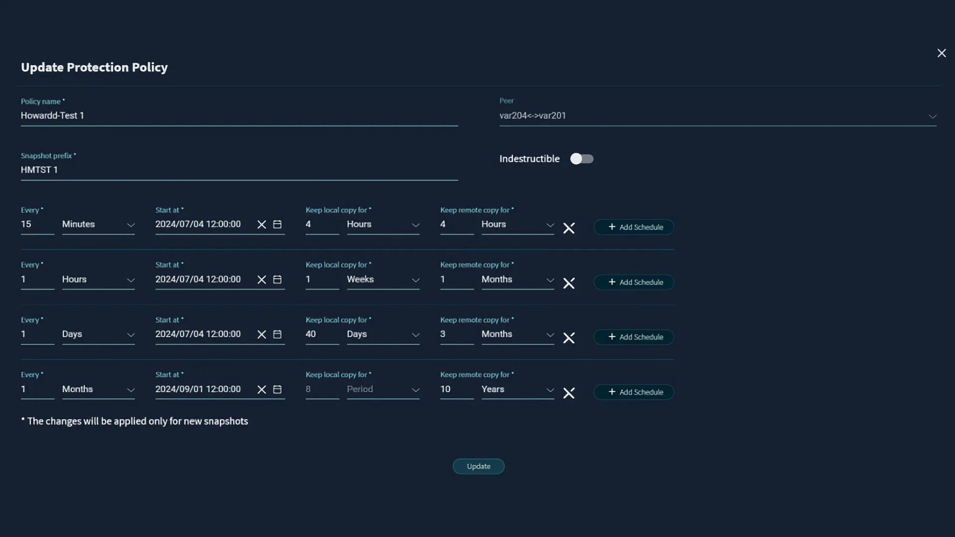
One policy can be used to protect multiple paths/buckets, allowing admins to create their own zinc, tin, and pewter protection levels. As mentioned above, snapshots of multiple paths taken at the same time are all consistent with each other without the need to define consistency groups.
VAST Replication
While snapshots are the first line of defense in any data protection plan, even VAST’s Indestructible Snapshots (TM applied for, patent application considered, etc.) are vulnerable to events that damage a whole VAST cluster. You must get data out of the data center to protect against fire, flood, earthquake, tornado, hurricane, typhoon, sharknado, or a steam tunnel explosion. The most effective way to get your data safely to another data center is replication.
VAST systems support multiple replication methods to support users' requirements for data protection, availability, and disaster recovery objectives.
Snap-to-Object – Replicates the data in a folder/bucket to an S3-compatible object store for data protection.
Native VAST Asynchronous replication leverages snapshots to periodically replicate a folder’s changes between VAST clusters.
Native VAST Synchronous replication ensures that all data is safely written to two VAST clusters with an RPO (Recovery Point Objective)
Snap-to-Object
Snap-to-Object extends the data protection provided by VAST snapshots off-site data protection by replicating snapshot data to an S3-compatible object store in another of the customer’s data centers or the public cloud. Users can control the replication frequency down to once every 30 minutes by time of day. The system writes the snapshot data to an S3 bucket in large, compressed, self-describing objects for efficiency.
Once snapshot data is in the cloud, the snapshot’s contents are available on the source VAST cluster through the read-only /.vastremote/policy/snapshot_time/ folder. All a user has to do to restore a file, or a thousand files, is copy the preserved copy from /.vastremote. It’s simple and safe enough for end-users to perform self-service restores.
Since the Snap-to-Cloud objects are self-describing, they contain all the metadata any other VAST cluster, including a VAST on Cloud cluster, needs to mount those objects in their own /vastremote folder hierarchy.
Asynchronous “Native” Replication
Snap-to-Object addresses users’ requirements for off-site data protection and long-term retention. The problem is that since Snap-to-Object stores its data in large objects optimized for cloud storage, users must restore their files/objects through the /.vastremote folder to some other location before using their data. As a result, Snap-to-Object provides many of the same benefits as traditional backup/restore solutions with the same extended RTO (Recovery Time Objective) issue since data isn’t available until the restore completes.
VAST Native Replication solves this problem by replicating data between multiple VAST clusters and maintaining the native data layout in the VAST DataStore at both ends. Users can access data on target clusters without waiting for data to be restored, minimizing RTO.
Native replication comes in two variations. Asynchronous replication periodically sends the changes to a protected folder in the VAST Element Store to the target clusters. Asynchronous replication will let you meet RPO (Recovery Point Objectives) of a few minutes. When you can’t afford any data loss at all, synchronous replication ensures your data is written to both target clusters before the write is acknowledged to your client.
Asynchronous Replication
As we saw when we discussed protection policies, asynchronous replication, sometimes also called point-in-time replication, is deeply integrated with the VAST snapshot mechanism. When a VAST admin sets up a replication policy, they define the frequency of snapshots and the retention periods at both the origin and target clusters. Since these snapshots are based on the global snaptime counter, all the folders scheduled for a snapshot at the same time will be captured simultaneously, ensuring consistency without the need for explicit consistency groups.
Once the protection policy is established, the origin cluster will send the protected path’s data to the target clusters, followed by the changes for each snapshot with remote retention selected. The target directory presents the last replicated state of the source directory, read-only, to prevent data integrity issues. Since the target folder is on an all-flash VAST system, it’s immediately available for analysis.
There’s full support for both graceful failovers when both systems can still communicate and graceless failovers when they can’t. Graceful failovers turn the source read-only, perform a final replication, make the former target read-write, and reverse the replication direction. In addition, administrators can fail over individual replicated directories for testing or to shift active workloads from one data center to another. The two systems will automatically resynchronize when reconnected after a graceless failover.
A VAST cluster can replicate a protected path to up to three other VAST clusters. Customers can configure replication QoS to prioritize traffic for selected protected paths or selected targets. In addition, the traffic between VAST clusters can be encrypted using mTLS (mutual TLS), which encrypts the data and provides mutual authentication for both clusters in the connection.
Minimizing Recovery Point Objective
Most storage systems that perform snapshot-based asynchronous replication allow users to take and replicate a snapshot as frequently as once every 15 minutes. While storage vendors like to call their snapshot frequency the system’s Recovery Point Objective (RPO), this ignores the time it takes to take and transfer each snapshot. More realistically, a 15-minute replication frequency would allow a user to expect to lose no more than 30 minutes of data, a 30-minute RPO.
While a 30-minute RPO is good enough for many use cases, other applications demand shorter RPOs. The low cost of VAST’s snapshots allows a VAST cluster to replicate data every 15 seconds, reducing the minimum RPO to under a minute.
VAST systems also monitor replication pairs for RPO compliance, generating alerts whenever a replication pair fails to sync for two replication periods.
Synchronous Replication For Maximum Availability
Simple, Powerful Policies
Since they’re based on the same underlying technology, VAST systems manage native async replication as an extension of the protection policies used to manage VAST Snapshots. When VAST clusters are replicating, each snapshot schedule has two retention periods, one for the local snapshot and one for the remote snapshots.
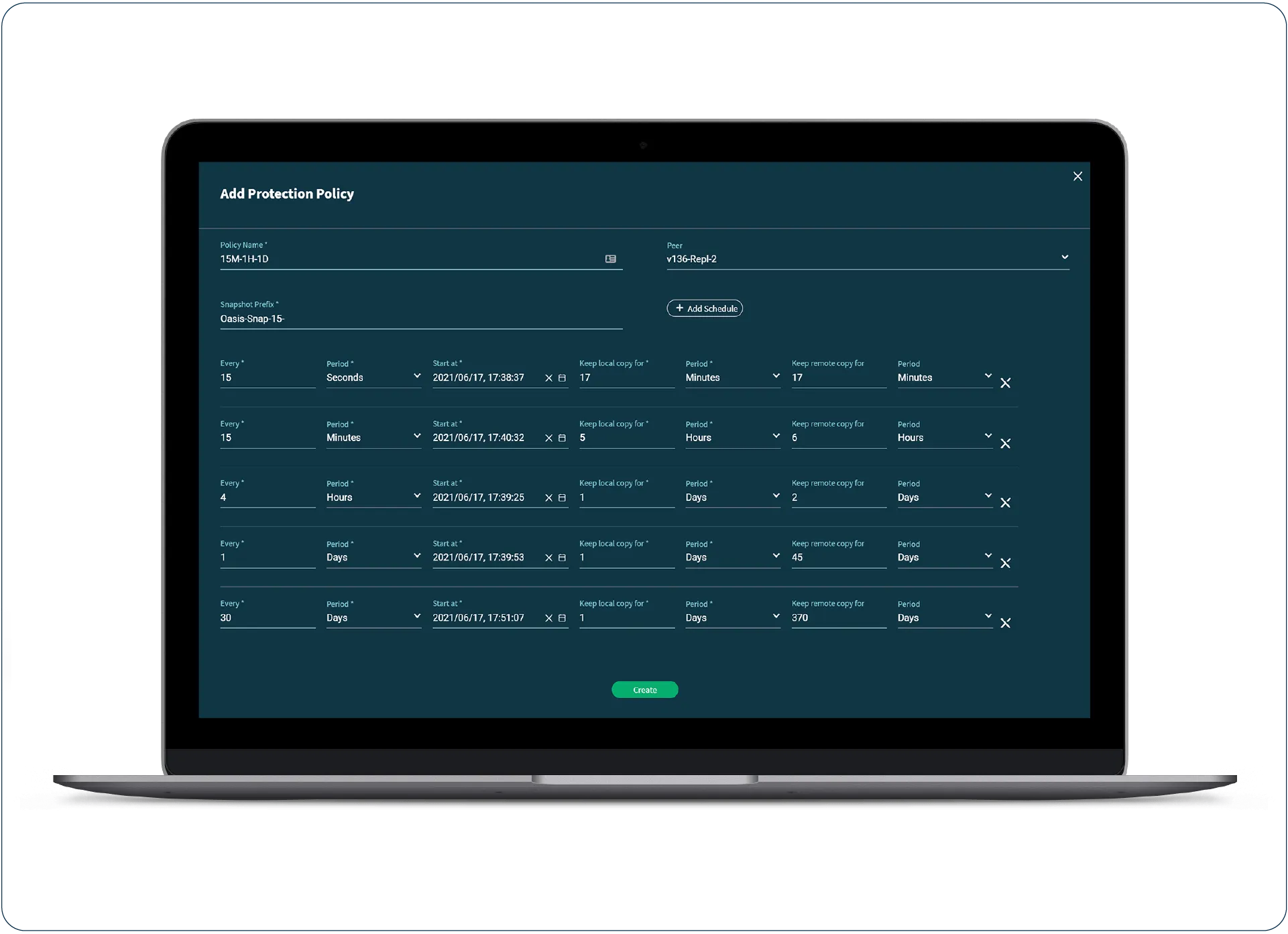
Minimizing Recovery Point Objective
Most storage systems that perform snapshot-based asynchronous replication allow users to take, and replicate, a snapshot as frequently as once every 15 minutes. While storage vendors like to call their snapshot frequency, the system’s Recovery Point Objective (RPO) ignores the time it takes to take and transfer each snapshot. More realistically, a 15-minute replication frequency would allow a user to expect to lose no more than 30 minutes of data, a 30-minute RPO.
While a 30-minute RPO is good enough for many use cases, other applications demand shorter RPOs. The low cost of VAST’s snapshots allows a VAST cluster to replicate data every 15 seconds, reducing the minimum RPO to under a minute.
VAST systems also monitor replication pairs for RPO compliance, generating alerts whenever a replication pair fails to sync for two replication periods.
Clone Snapshots Anywhere with Global Clones
Like many other modern storage systems, the VAST Data Platform can create a clone from any VAST Snapshot. The difference is that, unlike the clones on those other storage systems, VAST Global Clones aren’t limited to the same cluster as their source folder or even their source snapshot.
The VAST Element Store’s timestamp-based snapshots and write-in-free-space data layout allow VAST clusters to create clones with essentially no overhead. However, local clones aren’t the right solution for every problem. Most commonly, users don’t want to allow developers write access to their production systems at all or want to use computing resources in another data center, perhaps closer to the developers.
Global Clones allow VAST customers to create a clone on one VAST cluster from a snapshot on a remote VAST cluster. Once the global snapshot is created, the remote cluster can publish its content through one or more VAST Views providing access to the clone’s contents for users and servers in the remote site with all the performance of their VAST cluster.
Let’s take as an example Mammoth Pictures; they run their primary data center on their lot in Los Angeles, a smaller data center in the New York office, and rent space in a colocation center in Hollywood. When compute resources become scarce in their LA data center, Mammoth can create a clone of their data in their HollywoodCoLo to test their rendering algorithms on the latest GPUs there or just to stress-test the website before the release of next summer’s blockbuster.
Global Clones are based on VAST Replication and send data from a source VAST cluster to specified target VAST clusters for a protected path. The difference between Global Clones and clones made from replicated snapshots is what data is sent between the two sites and when it’s sent.
When the Mammoth replicates a daily snapshot to the New York office, the LA cluster sends a full copy of the data in the protected path to the New York cluster. Once that transfer completes, the LA cluster will take daily snapshots and send the differences between each snapshot and its predecessor to New York. The New York cluster holds and protects a full copy of the protected path plus the deltas for any previous snapshots retained in New York.
The HollywoodCoLo is configured to provide Global Clones for the same protected path. Each time the LA cluster creates or deletes a snapshot of the protected path, it sends metadata updates about those snapshots to the HollywoodCoLo cluster. When the studio wants to run a test render in Hollywood, they can select any of the snapshots on the LA cluster and create a clone on the Hollywood cluster, then publish it as a VAST View (Share/Export/Bucket) in Hollywood.

When they create the clone, the studio’s sysadmins can choose to create an Eager Clone, which would cause the system to perform a one-time replication of the protected path using the VAST Replication mechanism; or a Cached Clone, which fetches data from the LA cluster on access. Cached Clones reduce the impact of data gravity by only transferring the data their applications access, saving capacity on the target system and network bandwidth while still giving that application access to the full production dataset.
Cached and Eager clones are available to users and applications at the remote cluster seconds after creation. The VAST system will prefetch metadata and data using heuristics that learn the application’s read patterns to maximize performance as clones populate. As the term clone implies, new writes are stored locally.
The Access Layer
Providing Multiprotocol Access to the VAST DataStore
We’ve looked at how the VAST DataStore manages a VAST Cluster’s media, data, and most importantly metadata. But there’s more to a data platform, or even a just storage system, than just storing data. The system also needs to make that data available to users and applications, define and enforce access security, and enable cluster administration. That access, and the associated controls, are provided by the protocol layer of the VAST Data Platform’s stack.
Just as the VAST Element Store is a namespace abstraction that combines the best parts of modern file systems with the scale and extended metadata of an object store (not to mention the ability to manage structured tables), the Protocol Layer provides a protocol-independent interface to the individual elements in the Element Store.
Some vendors support new (S3), complex (SMB), or for native object stores simply foreign (NFS, SMB) protocols by integrating open-source projects like Minio and SAMBA into their products. While this lets them check the box for multiprotocol support, it means these additional protocols are really second-class citizens.
Because the actual back-end storage is designed for a single protocol, cross-protocol ACLs are difficult, especially when the storage doesn’t support an ACL concept such as deny. The other problem is that the open-source module is always running as a gateway process that, even if it doesn’t translate SMB directly into S3, still has to translate requests to fit the back-end storage. What’s more, most open-source, or even commercially available, protocol modules have limited scalability. Given all this, it became clear that VAST would be better off keeping protocol development in-house, which also allows VAST protocol modules to access the VAST Element Store more intimately than standard APIs would allow.
VAST develops all the protocol modules in-house as equals. The namespace abstraction provided by the Element Store enables VAST Data to add support for additional file, block, big data, and yet-to-be-invented protocols over time simply by adding additional protocol modules.
It also means that VAST systems provide similar performance through all the supported protocols.
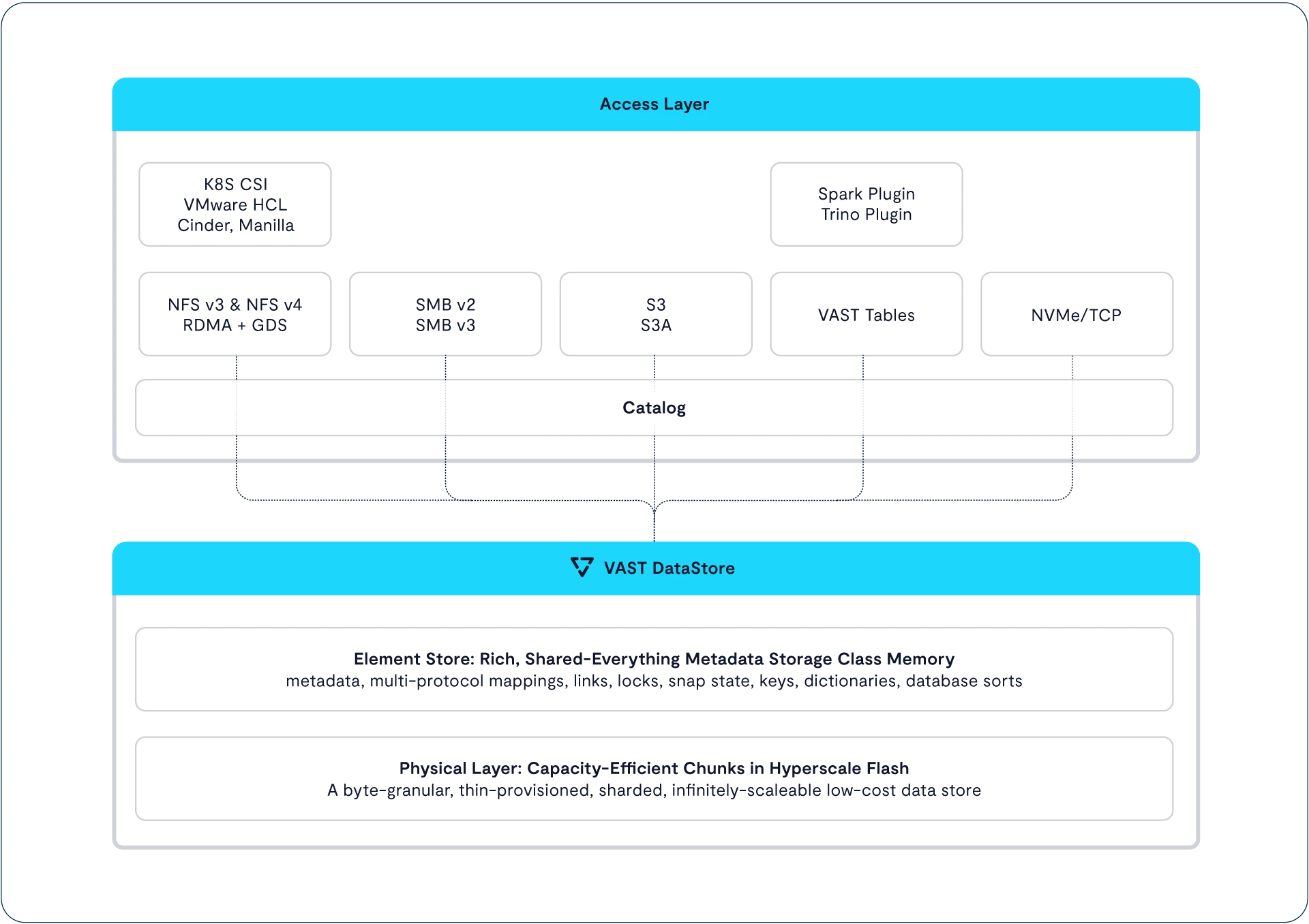
The individual elements in the VAST Element store are also protocol independent. This means all elements, and the entire capacity of the VAST cluster, can be made accessible by any supported protocol. This lets users access the same elements over multiple protocols. Here’s an example of multi-protocol access in practice: a gene sequencer stores genomic data via SMB; an application watching the folder on a Linux server via NFS notices the file, runs it through its inference engine, and writes its results as metadata tags via an S3 API call. Then this data can be made available via S3 to a pipeline build from some cloud framework.
VAST supports versions 3 and 4.1 of NFS for Linux and other open systems clients; versions 2.1 and 3.1 of SMB, the preferred file protocol for Macintosh and Windows computers; and S3, the de facto standard for object storage. Access to Table type Elements is provided via VAST SQL and associated plug-ins for Trino, Spark, and other platforms.
In late 2024 the VAST DataStore will include NVMe over TCP, the modern block access protocol, for access to Volume type Elements.
Multiprotocol ACLs
One challenge of providing truly useful multi-protocol storage is controlling access through the very different security models expected by Linux and other open systems, NFS users, and Windows SMB users.
Classic NFS follows the Unix file security model. Each file has a nine-bit security mask that assigns read, write, and execute permissions to the file's owner, a group, and any user that’s not a member of the group, known as Other. This model made aligning security groups with business organizations difficult by only granting permission to a single group.
Posix ACLs add flexibility by adding support for multiple named users and multiple named groups in the access control list for a file or folder.
The access control lists in Windows NTFS are significantly more granular, allowing administrators to control whether users can list the files in a folder, delete subfolders, or change the permissions of the folder for other users. Most significantly, Windows ACLs have a deny attribute that prevents a user or group from inheriting permissions from a folder’s parents.
NFS 4.1 defines a new ACL format that’s granular like Windows ACLs but just different enough to add another level of complication.
As we spoke with users, it became clear that most datasets have a dominant security point of view. Some shared folders will be used primarily by Linux servers with occasional access by Windows systems. Users wanted to manage access to these data sets with POSIX- or NFS 4-style ACLs.
The users we spoke to also had other folders primarily used by humans operating Macs and Windows PCs. Here they wanted the finer-grained access control and familiarity for the users provided by Windows ACLs.
Just as the VAST Element Store abstracts data from the file system and object store presentations, it also stores access control lists in an abstracted form. Those abstracted ACLs can be enforced as Unix Mode Bits, POSIX, Windows, or NFS 4 format ACLs as clients access the data via multiple protocols. Even with that abstraction, the SMB and NFS views of how ACLs should be processed, modified, and inherited are different enough that we let users assign any View in the system to present NFS- or SMB-flavor ACLs.
Note that a view’s flavor determines which type of ACLs are dominant, not whether the view presents itself as an NFS Export, an SMB share, or both, which is controlled separately.
NFS-flavor Views act as NFS clients would expect in every way. Users can query and modify ACLs using the standard Linux tools over NFS. Those ACLs will be enforced on users accessing via both the SMB and NFS protocols.
SMB-flavor Views are managed like Windows shares and allow users to set fine-grained Windows ACLs through PowerShell scripts and the file explorer over SMB. Those ACLs, including denies, are enforced on NFS as well as SMB access.
QoS Silences Noisy Neighbors
Most IT organizations have a historically well-founded fear that one or more performance-hungry applications will saturate any given storage system’s ability to deliver data and cause other applications to slow down.
Those performance-hungry applications are the data center equivalent of the frat bros who rent the apartment next to yours and play death metal all night: the proverbial noisy neighbors. Fear of noisy neighbors has been a key driver of data siloization, forcing organizations to have multiple solutions to provide dedicated storage for different applications or constituencies.
VAST systems provide multiple mechanisms that VAST admins can use to keep noisy neighbors from disturbing other applications.
Performance in the DASE architecture, in particular small I/O performance, is a function of the amount of CPU power available to process user requests. Admins can therefore allocate performance to applications, or user communities, by assembling server pools that dedicate the CPU power of a set of CNodes to those applications.
Server pools dedicate the performance of CNodes to a purpose, but that control is very coarse grained; after all, a CNode is a significant amount of computing power. For finer grained control VAST clusters have a more direct method to control the Quality of Service (QoS) provided.
Admins can assign any View (mount/share) QoS limits in terms of bandwidth and/or IOPS with independent limits for reads and writes. These QoS limits can be absolute or relative to the capacity used, or provisioned, for the View, allowing service providers to have a 200 IOPS/TB class of service.
VAST NFS
Parallel File System Speed, NAS Simplicity
Let’s look at each protocol in detail, starting with NFS.
NFS, the Network File System, has been the standard file sharing protocol for open systems since 1984. VAST’s NFS 3 implementation includes important, standardized extensions to NFS for security (POSIX ACLS), and data management (NLM).
Traditional NFS over TCP has been performance-limited because the TCP transport protocol will only send a limited amount of data before it receives an acknowledgment from the receiver. This limit on data in flight, sometimes called the bandwidth-delay product, restricts a single NFS over TCP connection from a client to a server to approximately 2 GB/s even on 100 Gbps networks.
Users have traditionally taken one of two complex approaches to solving this problem. They use multiple mount points, and therefore multiple connections to the NAS or switch to a complex parallel file system.
Multiple mount points provide a limited performance boost at the cost of more complicated data management and do nothing to speed up a single application accessing a single mount. Parallel file systems require client-side file system drivers that limit and complicate client OS choices and updates.
While NFS is almost 40 years old, that doesn’t mean it hasn’t been modernized and accelerated over those 40 years. NFS v4 introduces a much higher security model than NFS v3, with more granular ACLs and encryption in flight. Meanwhile, a series of NFS enhancements allow VAST systems to deliver the performance of a parallel file system without all the complexity introduced by parallel file systems.
Accelerating NFS for the AI Era
VAST systems support three technologies to increase the performance of NFS-connected hosts:
nconnect – A Linux mount option that spreads NFS over multiple TCP connections
Multipath - Spreads multiple TCP connections from nconnect over multiple physical connections
NFS over RDMA - Uses RDMA instead of TCP for low latency transport
nconnect for Multiple TCP Sessions
The first step to boosting NFS performance is the nconnect NFS mount option, which was added to the NFS client with the Linux 5.3 kernel in 2019. When an NFS client mounts an export with the nconnect=n option, it will load balance access to that export across n TCP sessions, not just one.

Where standard NFS over TCP maxes out at about 2 GB/s, connections with nconnect=5 or 8 can see 10 GB/s bandwidth with a 100 Gbps Ethernet connection.
VAST Adds Multipath
The nconnect mount option spreads the NFS traffic between an NFS client and an NFS mountpoint over multiple TCP sessions. As we’ve seen, this NFS connection exceeds the 2 GB/s bandwidth limit of a TCP session, but those TCP sessions are between one IP address, and therefore physical interface, on the client and one IP address on the NFS server.
That means the bandwidth boost provided by nconnect is limited to the speed of a single network connection; good for servers with 100 Gbps Ethernet cards, not so good for the video editor on a workstation with two 10 Gbps Ethernet cards.
To solve this problem VAST developed an open-source NFS driver that spreads the multiple TCP connections created by nconnect across the lists of client and server IP addresses specified. For example, if a client had mount options of:
Nconnect=8,ClientIP=10.253.3.17-10.253.3.18,ServerIP=10.253.4.122-10.253.4.25
The NFS client will set up 8 TCP sessions connecting both client IP addresses to all four server IP addresses, as shown below.
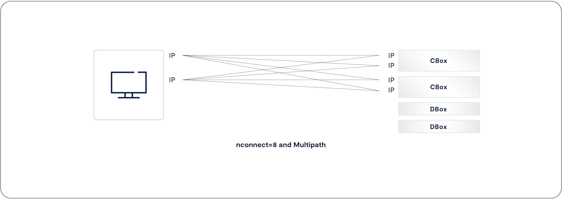
The VAST patch for both NFS 3 and NFS 4, which we’ve submitted upstream for inclusion in Linux distributions, not only spreads the traffic across multiple 10 Gbps links for that video edit station, but because each virtual IP address sends traffic to one CNode using multiple server addresses, it also spreads the traffic across multiple CNodes. The metadata in shared SCM on the VAST cluster serves as a single source of truth, allowing the VAST cluster to process parallel I/O across multiple CNodes and still remain strictly consistent.
Using multiple network paths also boosts resilience for critical workloads by transparently routing traffic to the surviving link.
NFS over RDMA (NFSoRDMA)
In the mid-2010s, Oracle and other key contributors got together and updated NFS to use RDMA (Remote Direct Memory Access) to transport NFS RPCs between the client and server instead of TCP. Thanks to their work, NFSoRDMA has become part of all the major Linux distributions.
RDMA transfers data across the network directly into the memory of the remote computer, eliminating the latency of making copies of the data in TCP/IP stacks or NIC (Network Interface Card) memory. The RDMA API, known as RDMA Verbs, is implemented in the RNIC (RDMA NIC) offloading the transfer from local memory directly into memory on a remote computer and eliminating the user space/kernel space context switches that add overhead to TCP connections.
RDMA Verbs were first developed for InfiniBand so NFSoRDMA can, of course, run over standard InfiniBand networks. More recently, RDMA Verbs have been built into Ethernet RNICs using the RoCE (RDMA over Converged Ethernet). This brings NFSoRDMA to Ethernet as well as InfiniBand data centers. RoCE v2 runs over UDP and doesn’t require any special network configuration beyond enabling ECN (Explicit Congestion Notification), a standard feature of enterprise Ethernet switches since 10 Gbps networking ruled the roost.
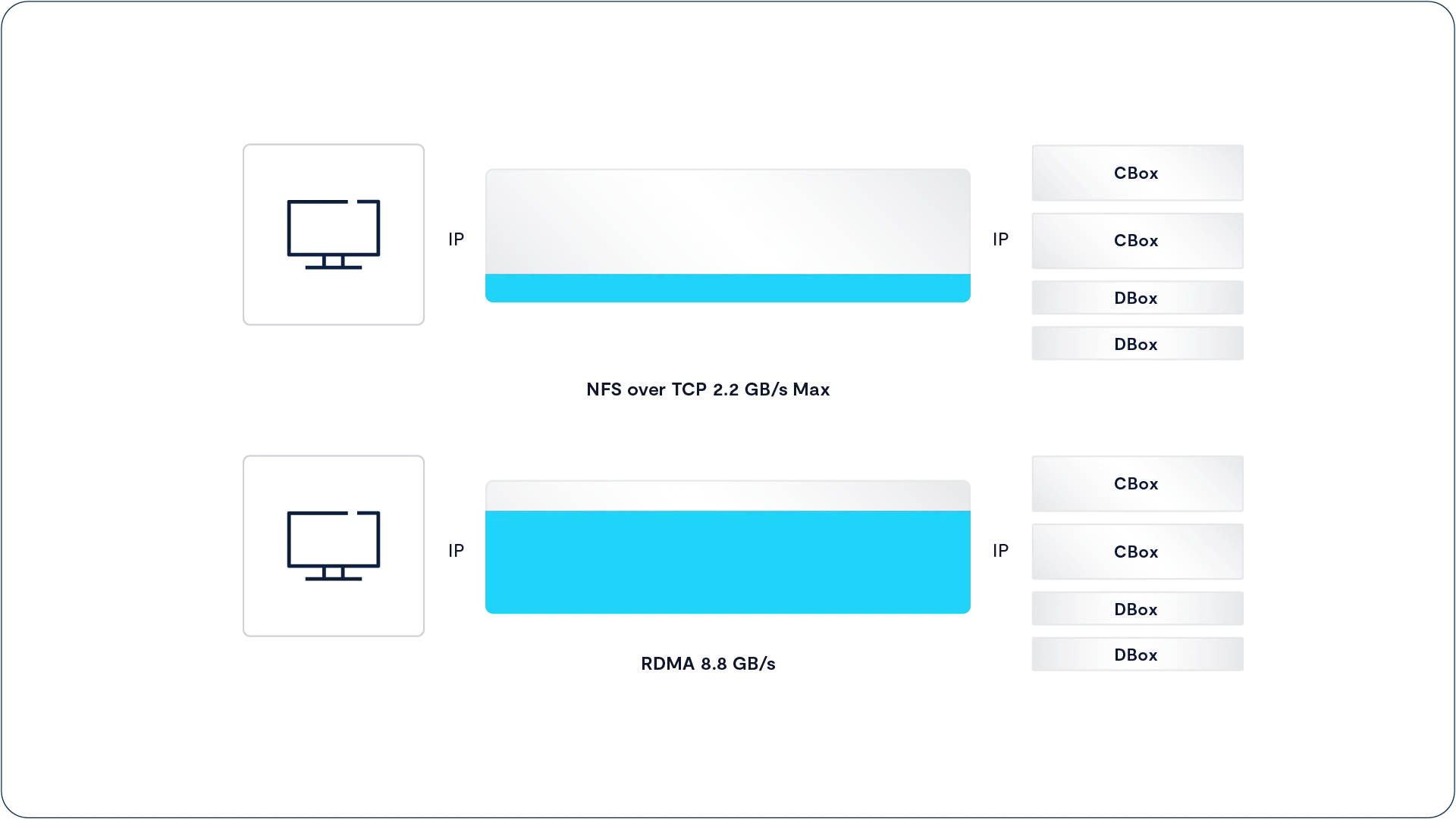
The net result is that where a single NFS over TCP session to a VAST Cluster is limited to 2 GB/s, a single NFSoRDMA session can deliver up to 70% of a 100 Gbps network’s line speed, or 8.8 GB/s.
But the real beauty of NFSoRDMA lies in the simplicity of deployment: the NFSoRDMA client is standard in major Linux distributions, so it doesn’t require any of the kernel patches or client agents that can make deploying and maintaining high-bandwidth parallel file system storage problematic.
With VAST NFS Means Now for Speed
In the past, users have had to use complex parallel file systems because the NFS servers of the day couldn’t deliver the performance HPC, AI, and media workloads, among others, required.
Today, performance enhancements from nconnect to RDMA make NFS the protocol of choice for your most demanding workloads. The graphic below shows how each of these features involve more of the host resources to deliver greater performance. The active components in each data transfer are shown in blue.
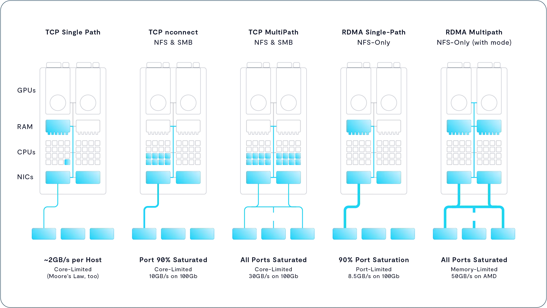
NFS Extensions
VAST systems support several standard extensions to POSIX Access Control Lists (ACLs)
VAST is one of the few companies to implement ACLs that conform to the POSIX specification, allowing a system administrator to define broader and more detailed permissions to files and folders than is possible with the simplistic Unix/Linux model. (This model is limited to defining read/write and execute permissions to the root, a single user “owner” of the file or folder, and a single group.) Unlike Linux mode bits, POSIX ACLs are very flexible and allow administrators to assign permissions to multiple users and groups.
NLM Byte-Range Locking
VAST NFS also supports the NLM byte-range locking protocol defined in the standard Linux NFS-util. NLM, which originally stood for Network Lock Manager, defines a mechanism for NFS clients to request and release locks on NFS files and byte ranges within the files. NLM locks are advisory, so clients must test for and honor locks from other clients. NLM provides the support for shared and exclusive locks to applications and is designed for parallel applications where many byte-ranges can be locked concurrently within a single file.
VAST’s approach to NLM locking is inherently scalable because locking and lock management is fully distributed across the VAST Cluster. VAST Clusters don’t implement a centralized lock manager function or process. Instead, lock information is stored as extended file system metadata for each file in the VAST V-Tree. Since all the system metadata is available to all the VAST Servers in the cluster, each VAST Server can create, release, or query the lock state of each file it’s accessing without the central lock manager server that can so often become a bottleneck on other systems.
NFS Version 4
NFS version 4 was a major re-write of the NFS protocol and provides a significant improvement over NFS v3, especially where security is concerned. Unlike NFS v3 (and S3) NFS v4 is a stateful protocol that includes secure authentication via Kerberos and the detailed ACLs mentioned above.
VAST systems support the session-based NFS v4.1 over both TCP and RDMA, including support for NFS 4 byte-range locking, Kerberos authentication, Kerberos encryption in flight, and NFS v4 ACLs.
VAST SMB
File Services for Windows and Macintosh
While NFS is the native file access protocol for Linux and most other Unix derivatives, NFS isn’t the only widely used file protocol. Windows and Macintosh computers use Microsoft’s Server Message Block (SMB) protocol instead of NFS. The SMB protocol is also sometimes known as CIFS after an unsuccessful proposal by Microsoft to make SMB 1.0 an internet standard as Common Internet File System.
SMB is such a complex, stateful protocol that many NAS vendors choose to acquire it through the open-source SAMBA project or from one of the handful of commercial vendors that sell SMB code. Unfortunately, all the available SMB solutions have limitations, especially around scaling, that keep them from being good enough for VAST.
Instead, VAST developed our SMB protocol in-house to take full advantage of the DASE architecture storing session state in the cluster’s shared SCM pool to allow SMB service across all the cluster’s CNodes. Because the VAST DataStore is fully multi-protocol, SMB users can access the same files and folders as users accessing the system via NFS and/or S3.
File access to the VAST namespace is controlled by VAST Views. A VAST View is a protocol-independent version of an NFS Export and SMB Share. Administrators can enable NFS and/or SMB access to a view and set the access control flavor of the View to NFS or SMB.
VAST systems support SMB 2.1 and 3.1 including SMB Multichannel for enhanced throughput.
SMB Server Resilience
Every time an SMB client opens a file on an SMB server, the two systems assign an SMB handle to identify the connection. This requires both the client and SMB server to retain state information relating clients, files, open modes, and handles.
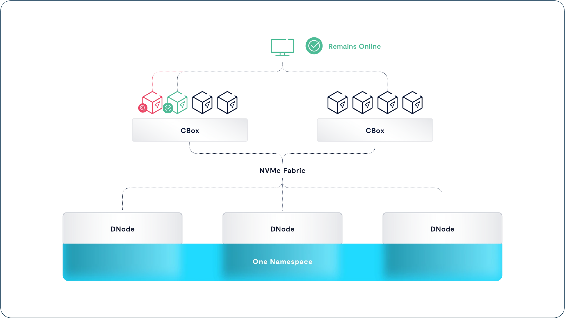
Many scale-out storage systems force users to manually retry or reconnect after a node failure, because while another node may take over the virtual IP address from the failed one, the dynamic state information, like handles, is lost. For an SMB client to automatically recover from a node failure, the state information has to be shared, and the shared-nothing model breaks down.
DASE and SMB Failover
In a VAST server, dynamic handles, file leases, and all the other state information that defines the relations between SMB clients and servers is stored in shared SCM (Storage Class Memory) in the cluster’s VAST Enclosures. This allows the surviving VAST servers in a cluster to not only assume the IP addresses of a VAST server that goes offline, but also to resume where the offline server left off, reading the connection’s state from SCM.
The SMB client sees the equivalent of a transient network glitch as the system detects a failed VAST server and recovers; exactly what SMB 2.1’s resilient handles were designed to accommodate. No lost handles, and most importantly, users and applications continue as if the failure never happened.
VAST S3
Object Storage for Modern Applications
Amazon’s S3 (Simple Storage Service) protocol, or more accurately the protocol used by Amazon’s S3, has emerged as the de-facto standard for object storage. In no small part that’s because it lets developers support both on-premises object stores such as VAST’s VAST DataStore and cloud storage such as Amazon S3 and its competitors.
VAST’s Protocol Manager exports S3 objects using HTTP GET and PUT semantics to transfer an entire object via a single request across a flat namespace. Each object is identified and accessed by a URI (Universal Resource Identifier). While the URIs identifying files can contain slashes (/s) like file systems, object stores don’t treat the slash character as special, so that it has the ability to emulate a folder hierarchy without the complexity a hierarchy creates – slashes are just another character in an internal element identifier.
VAST Objects are stored in a similar manner to files, with the difference being that an S3 object includes not just its contents, but also user-defined metadata that allows applications to embed their metadata about objects within the objects themselves.
While object storage has classically been used for archival purposes, the emergence of fast object access and, in particular, all-flash object storage, has extended the use cases for which object storage is appropriate. For example, many Massively Parallel Processing (MPP) and NoSQL Databases use object storage as their underlying data repository.
VAST DataStore systems support a subset of the S3 verbs that are offered as part of Amazon’s S3 service. Whereas many of Amazon’s APIs are specific to their service offering, VAST Clusters expose the S3 verbs that are required by most applications that benefit from an all-flash on-premises object store. That excludes tiering; a VAST system provides one tier, all-flash, and AWS-specific factors, like the number of availability zones each object should be replicated across.
As with VAST’s NFS offering, S3 performance scales as enclosure and server infrastructure is added to a cluster. For example, a Cluster consisting of 10 enclosures can be read from at a rate of up to 230 GB/s for 1 MB GET operations, or at a rate of 730,000 random 4 KB GETs per second.
NVMe-Over TCP Block Services for the 21st Century
From their very inception, file and object storage systems were designed to provide a pool of shared storage that multiple computers could access simultaneously. As a result, large-scale applications that use many servers to process a common data set are only practical because of this sharing.
However, some applications are somewhat more possessive about their data and insist on storing their data on disk drives, or at least virtual disk drives, that are entirely in their control. These applications generally involve some sort of tightly coupled application cluster. For example, many clusters only allow a single member to access a logical disk; they use device reservations to pass ownership of the logical disk from member to member when a node dies.
For the last 20 years or more, enterprises have addressed this problem with Fibre Channel SANs that connect their servers to expensive storage arrays. Those arrays slice and dice the SSDs and/or HDDs they control into virtual disk drives. Those virtual disks appear as locally attached SCSI devices to the server’s operating system. Fibre Channel and iSCSI (the red-headed stepchild for Ethernet), simply transport SCSI between servers and array controllers. Each SCSI command reads or writes some number of 512-byte blocks from a starting LBA (Logical Block Address) starting at 0 on the logical disk we, for indefinable reasons, still call a LUN (Logical Unit Number – the drive’s address on a SCSI bus).
As SSDs got more sophisticated, the industry developed NVMe (Non-Volatile Memory express) as a replacement for SCSI as the low-level command protocol between servers/controllers and SSDs. Because it was designed specifically for SSDs, NVMe takes advantage of the SSD’s ability to process multiple requests in parallel, replacing SCSI’s single command/data queue with 64K queues reducing latency.
NVMe over Fabrics (NVMe-oF) extends the NVMe protocol across a resilient network, the fabric, just as Fibre Channel and iSCSI extended the SCSI protocol. The difference is that networks, like SSDs, have gotten smarter in the years since Fibre Channel was developed and NVMe-oF can use those smarter networks as its fabric. VAST’s DASE architecture uses NVMe over RDMA (Remote Direct Memory Access) to give the CNodes (server nodes) in the cluster ultra-low latency access to the SSDs in the cluster.
The VAST DataStore couldn’t really deliver Universal Storage without providing storage for those applications, users, and admins, that require block access to their data. Because we don’t believe in doing things the old way, we’re providing block storage with NVMe over Fabrics—more specifically NVMe over TCP (NVMe/TCP).
VAST systems support NVMe/TCP as an access protocol alongside NFS, SMB, and S3. It will access LUNs that are stored as Elements in the VAST Element Store. NVMe/TCP has lower network requirements than NVMe over RDMA and provides comparable performance in many benchmarks.
All the major operating systems and hypervisors include NVMe over Fabrics initiators that will allow them to map LUNs on their VAST systems to drives on their servers using NVMe/TCP. Since any CNode in a VAST cluster can process any request for data from a LUN Element as well as any other CNode, there’s no need for special ALUA multipath drivers. Users can use the standard multipath driver in their OS or hypervisor and still get optimal performance and resilience.
Ecosystem Integrations
The VAST DataStore was designed for modern applications in modern data centers. That means a data center where resources are allocated and managed by automated orchestration systems using APIs, not storage administrators clicking through GUIs. VAST DataStore has, as discussed above, an API-first design where all management functions are designed into the REST API first, and the GUI consumes the same REST APIs that our customer’s platforms and scripts do.
Kubernetes CSI
Containers are the latest, most efficient way to deploy applications, which is why we deploy VAST Servers in containers ourselves. Kubernetes, originally developed at Google and now run by the Cloud Native Computing Foundation, has become the dominant orchestration engine for containers. Kubernetes automates the provisioning and management of microservices-based applications in pods of containers across a cluster of X86 server nodes.
As users deployed more complex and data-intensive applications in containers, the container community added Persistent Volumes to containers and Kubernetes to provide storage for these applications. Kubernetes supports a wide range of file, block, and cloud storage providers for Persistent Volumes using the CSI (Container Storage Interface). In addition to Kubernetes, VAST users running Apache Mesos and Cloud Foundry can also take advantage of storage automation via CSI.
VAST’s CSI driver provides an interface between the Kubernetes cluster control plane and a VAST DataStore cluster. This allows the Kubernetes cluster to provision folders in an NFS Export as Permanent Volumes, define the volume’s size with a quota, and publish the volume to the appropriate pods.
Following the open and open-source philosophy behind CSI, the VAST CSI driver is open source and available to anyone interested at https://hub.docker.com/r/vastdataorg/csi.
Manilla
VAST’s CSI driver provides a standardized interface a Kubernetes cluster can use to provision Persistent Volumes, in the form of mountable folders, for pods of containers.
VAST’s Manilla Plug-in provides a tighter connection between a VAST cluster and the OpenStack open-source cloud platform. In addition to the basics of publishing volumes for VMs, as CSI does for containers, Manilla also automates the creation of NFS Exports and setting the Export’s access list of IP Addresses.
Manilla allows large operators to automate the process of provisioning Kubernetes, or OpenShift clusters, creating Exports private to each cluster, via OpenStack while provisioning volumes to container pods via CSI.
GPU Direct Storage
The GPU servers running artificial intelligence applications process orders of magnitude more data than general-purpose CPUs possibly could. Even with multiple 100 Gbps NICs, the GPUs would spend too much time waiting for data to be copied from a NIC data buffer into CPU memory and only then into the GPU’s memory where it could be analyzed.
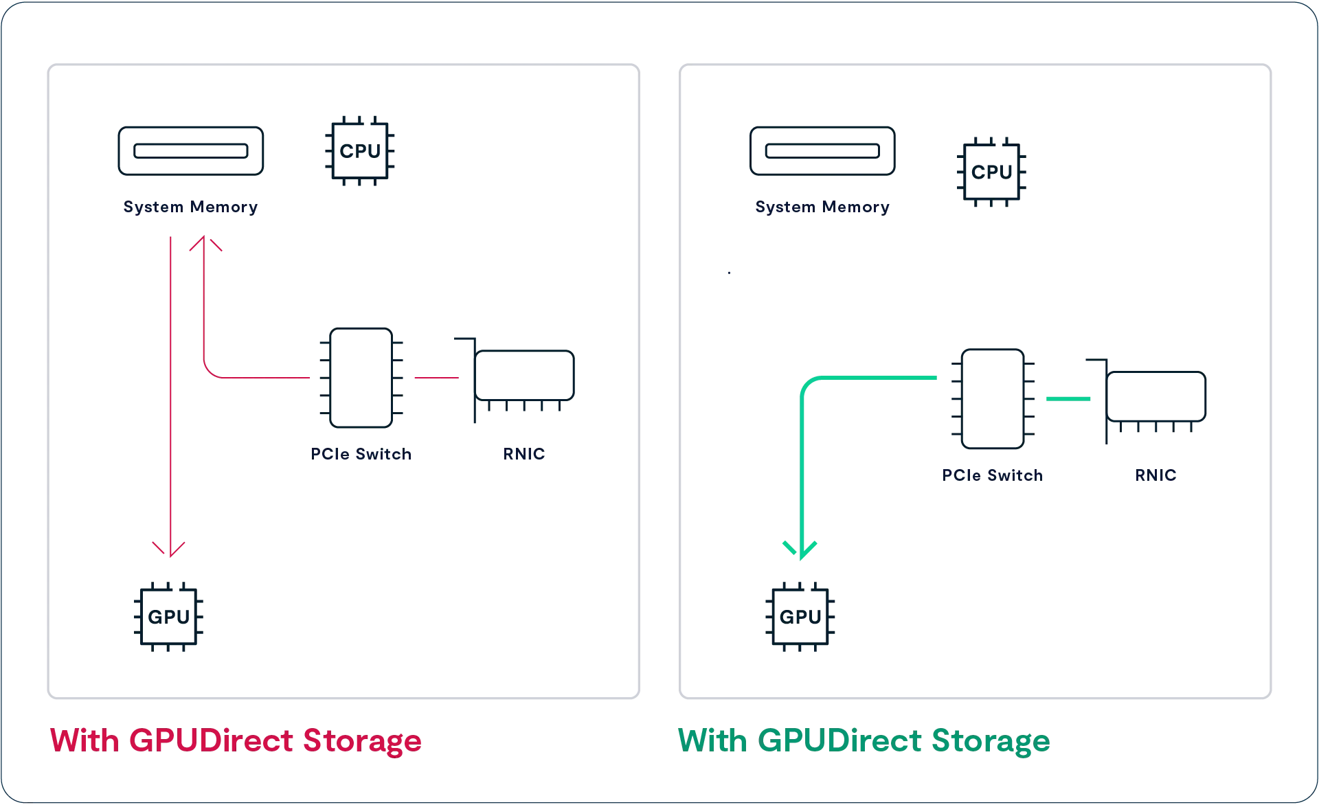
NVIDIA’s GPUDirect Storage provides a direct RDMA path for NFS data from an RNIC into the memory of a GPU, thus bypassing the CPU and the CPU’s memory. GPU Direct Storage (GDS) vastly increases the amount of data GPUs can access by eliminating the main memory-to-GPU bandwidth bottleneck of 50 GB/s. Using GDS the server can transfer data into the GPU from multiple RNICs in parallel, boosting total bandwidth to as much as 200 GB/s.
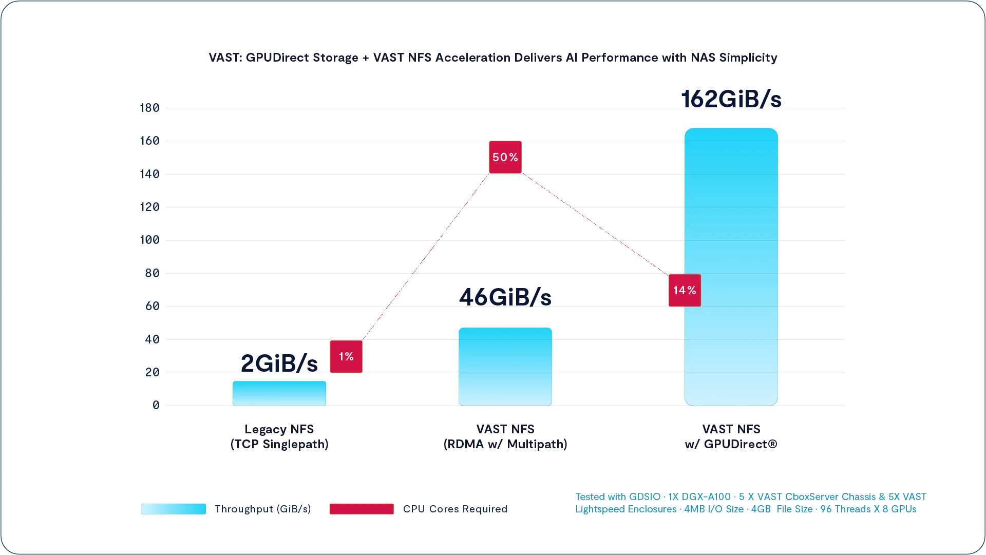
GPU Direct Storage also reduces the overhead of accessing storage. When we tested a VAST Cluster with an NVIDIA DGX-A100 GPU server, as shown in the chart above, the combination of NFS over RDMA and multipath load balancing across the DGX-A100’s eight 200Gbps HDR InfiniBand boosted total bandwidth from the NFSoTCP’s 2 GiB/s to 46 GiB/s. However, moving all that data through main memory to the GPUs eats up half the DGX-A100’s 128 AMD ROME cores.
Switching to GPU Direct Storage not only raised throughput to 162GiB/s but also reduced the amount of CPU required from 50% to 14%.
NUMA-Aware Multipathing
The PCIe slots, like the memory sockets, in a modern server are directly connected to one of the two CPUs. The result is NUMA (Non-Uniform Memory Access) where a process running on CPU-A can access memory directly connected to CPU-A faster than memory connected to CPU-B. Access to remote memory has to cross the bridge between the two CPU sockets and the bandwidth of that channel can become a bottleneck.
GPU Direct Storage accesses perform RDMA transfers from the RNIC in one PCIe slot to the GPU in another slot. The NFS multipath driver is NUMA-aware and will direct data from the VAST cluster to an RNIC on the client that’s connected to the same CPU/NUMA node as the GPU that will process the data. This keeps GDS traffic off the CPU-CPU bridge and away from that bottleneck.
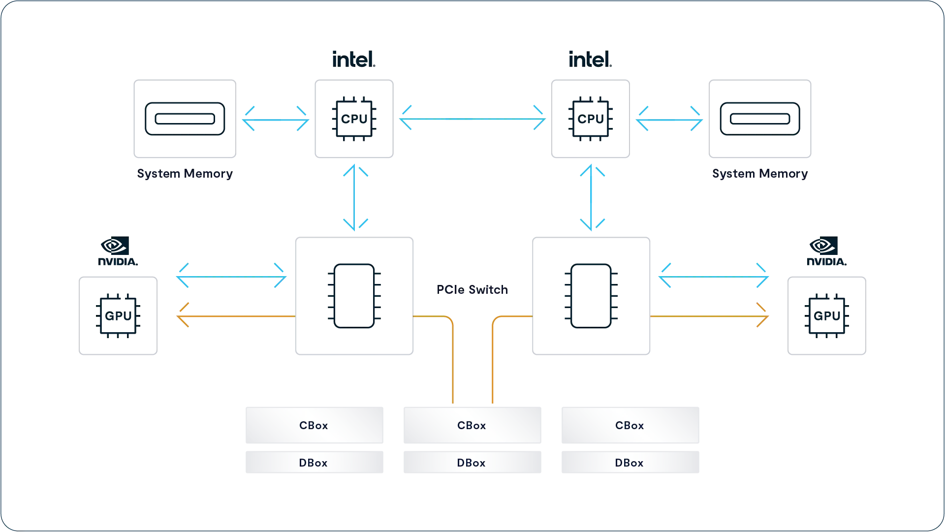
Ecosystem Validations
Keeping things simple has always been one of the key design tenets of the VAST DataStore. One affordable tier of flash is simpler than a complex tiered architecture, and standard NAS protocols are simpler than SANs and parallel file systems.
Supporting standard protocols also makes it simple to use VAST as the datastore for a wide range of applications. Even though they use standard protocols, some software vendors certify or validate datastores and VAST has many such validations including:
VMware vSphere – Validated as an NFS Datastore for vSphere
Commvault
Veritas
Veeam
Etc., etc.
More to Come
As the abilities of the VAST Data Platform grow with each new release, so do the opportunities for deeper ecosystem integrations. We’re working with vendors to use the VAST Catalog to replace the time- and resource-consuming file system walks they now perform. This will allow backup applications, workflow managers, and other data movers to quickly find the files that have changed between snapshots.
NVIDIA DGX H100 SuperPod Validation
NVIDIA’s DGX SuperPod is an engineered AI supercomputer using NVIDIA’s GPU-optimized DGX servers. The latest generation of SuperPod uses 127 DGX H100 servers each with eight H100 GPUs and eight 400 Gbps InfiniBand ports.
VAST was the first, and as of this writing is the only, NAS solution certified by NVIDIA as a datastore for SuperPod implementations. All the other certified solutions are based on much more complicated parallel file systems. See https://vastdata.com/press-releases/vast-data-achieves-nvidia-dgx-superpod-certification
The VAST DataSpace
VAST Goes Global
The VAST DataStore provides a fast, reliable repository for structured and unstructured data presenting a single global namespace for exabytes of data. Given the limitations of physics (Data can’t travel faster than the speed of light) and networking technology, the globe that global namespace can effectively serve is practically limited to a single data center or data center neighborhood like all the CoLos and cloud providers clustered in northern Virginia.
The VAST DataSpace solves that problem by joining VAST clusters into a constellation that can present a global namespace across multiple locations worldwide and potentially into low earth orbit. Once that constellation of clusters is joined into a VAST DataSpace, the administrator of that DataSpace can present folders to users and hosts in multiple locations simultaneously, delivering local performance and read-write access.
Any cluster in a VAST DataSpace can present any folder/bucket from its namespace to one or more satellite clusters where users can read or write to this Global Path as if it were just a folder in the local namespace. The VAST DataSpace makes your data available where you need it, whether that’s sharing data generated at the edge with servers at the core or shifting an inference stage to the latest GPUs in the cloud.
Those satellite clusters cache the Global Path in their local DataStores fetching data from the originating cluster on first access. All the folders holding a Global Path are fully read/write on all the clusters that hold that Global Path. In all cases, strict data consistency is ensured by read and write leasing mechanisms we’ll discuss below.
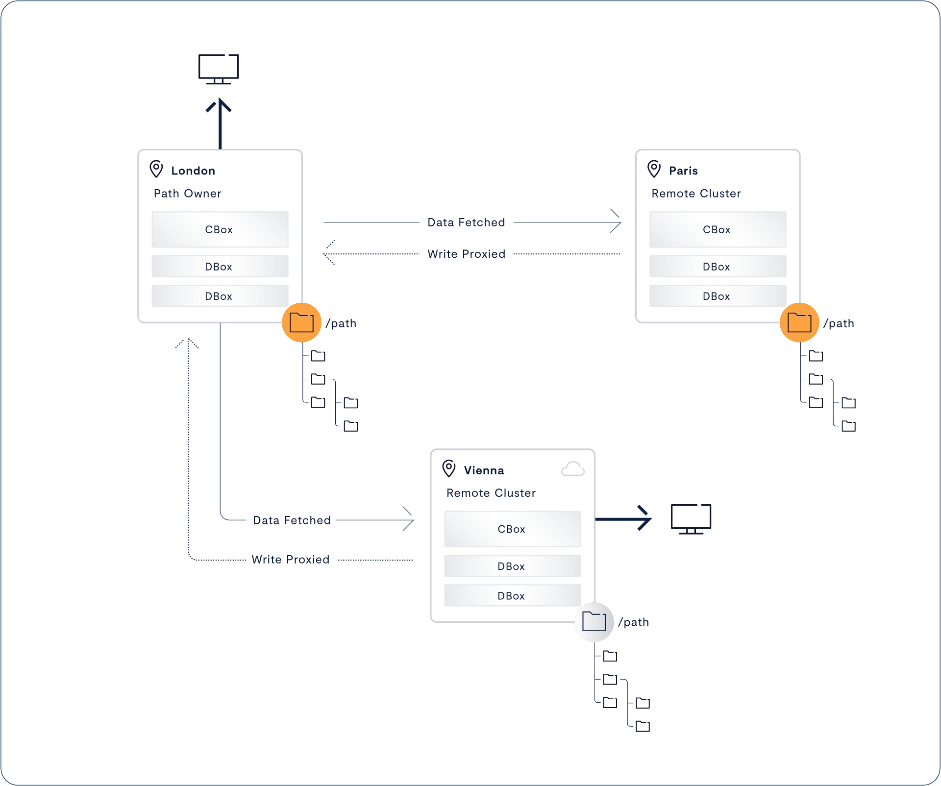
In the DataSpace shown above, the customer has created a Global Path (/path) on their cluster in London, then made that path available to users, and of course applications, in Paris, and Vienna.
Eventually Consistent Isn’t Consistent Enough
Most global namespace solutions periodically synchronize the data in satellite locations with a central copy that’s frequently stored in an object store. The result of this periodic synchronization is that these solutions are only eventually consistent, which is a less scary way of saying that they are inconsistent. Multiple users accessing the same file simultaneously may see different data. If a customer only synchronizes each of their clusters once an hour, their users in one location may see data that was overwritten by a user in another location several minutes ago.
Even worse, if a user in New York edits the same file as a user in LA within the one-hour replication period, the changes the user in LA made would be lost when the updated version from New York is replicated the next time. Eventually, consistent namespaces resolve these change collisions with a combination of Last-Writer-Wins semantics and file versioning.
When there are versions of a file created in multiple locations, the system saves the version with the latest time stamp, holds the version(s) from other locations as previous versions of the file, and in the best case, sends a message to all the users who wrote to that file so they can manually merge their changes.
Some global file solutions, like NAS appliances, address this with file locks; when a user in NY opens a file for writing via a stateful protocol like SMB, the system locks that file. Any other user that tries to open that file with an SMB-aware application like Excel will see, “Howard has that file open – Do you want to open a read-only copy?”. That works pretty well for applications like Excel, where users can access a file sequentially (don’t start about Google apps and collaboration here that’s an application-level thing, Microsoft 365 has it for Excel, too but this is a storage thing that works for applications that are less smart about collaboration than that but Excel is a good example anyway because everyone in corporate America has seen the message above so stop being so pedantic and get off my back) under SMB, but it doesn’t work for stateless protocols like NFS 3 and S3, or for applications where users need to read consistent data.
Write Leases Ensure Consistency
Unlike eventually consistent solutions that provide Last Writer Wins consistency, The VAST DataSpace uses write leases to ensure strict consistency. Write leases ensure that only one VAST cluster can have a write lease for a given Element (File/object/path) at any moment in time but, more significantly, that any application reading data from any location in the VAST DataSpace always gets the latest version of any data they read, even when that Element was last written seconds ago on another cluster.
Suppose Mammoth Pictures published the IronGiantII path from the VAST cluster in the LA office, where the animation artists work, to VAST clusters in the Hollywood CoLo that holds the studio’s render farm and the cluster in NY, where execs watch dailies. Since the LA office cluster replicates data to the other two locations, the LA office system initially holds the write leases for all the files and folders in that path.
When a user reads from a file or GETs an object on the protected path from any cluster other than the owner, the cluster servicing the read checks to see if any write leases were taken on the element being read since the local copy was updated. If no write leases were issued, the local copy is up-to-date, so the cluster serves the request from the local copy. If write leases were issued for the requested data since the last time this cluster fetched the element being accessed, the system will fetch the latest data from the owner.
When we say a cluster fetches data, we don’t mean the cluster fetches the latest version of the Element, copying gigabytes of data even if only a few kilobytes have changed. Instead, VAST clusters exchange data about which data chunks within that Element changed and only exchange those changed chunks plus any additional chunks the prefetch algorithms predict will be needed shortly.
When a cluster in the DataSpace receives a write or PUT, it requests a write lease on the element being written. When a write lease is granted, the cluster accepts writes. In DataSpace 1.0, the cluster accepting writes proxies those writes synchronously to the cluster that owns that element. If a cluster requests a write lease to an element with a write lease outstanding, that request will be declined, and where possible, the system will respond as if that file were locked via the requesting protocol.
Clusters reading the elements in question will fetch data directly from the origin cluster even if that cluster hasn’t yet synced with any other. An example would be servers in the HollywoodCoLo streaming logs into a folder read by the LA data center monitoring systems. When the log analyzer in LA reads a log file, it can see the entries at the end written seconds ago in Hollywood because it’s reading that data directly from Hollywood.
As DataSpace evolves, the ownership and lease management functions will become portable and more granular. This portability will allow applications to write data to their local cluster while maintaining strict consistency. A movie studio could, for example, assign the write lease for the “Dailies” folder to the VAST cluster on location, or a research institute configure its systems so their DNA sequencers write data locally. With the release of The VAST DataEngine VAST operators will be able to leverage the intelligence provided by The VAST DataEngine to prepopulate data to the location it will be processed next.
In future releases, the DataSpace will also move into the realm of real-time applications adding synchronous replication to create active-active clusters that let customers move workloads between data centers transparently to balance their loads, better utilize specialized compute resources like GPU servers, and of course, provide zero RPO disaster recoveries.
VAST Cloud Instances
VAST Cloud Instances are VAST Clusters that run on public cloud virtual machine instances instead of on-premises hardware. VAST cloud instances allow VAST customers to use public cloud services and compute resources to process the data they keep in their VAST DataSpaces. Media customers can use VAST cloud instances to burst rendering or transcoding tasks to GPU servers in the cloud, and everyone’s developers can try the latest tools and services with real data.
VAST customers can install VAST Cloud Instances into their VPCs (Virtual Private Clouds) from their cloud provider’s marketplace (AWS, GCP, and Azure instances should all be available by Q1 2024). Since the public cloud providers don’t offer shared NVMe over Fabrics SSDs VAST Cloud instances use the local NVMe SSDs provided with the cloud instance as their primary storage location.
Ephemeral Clones
Local NVMe SSDs provide the high performance that lets a single cloud instance provide the services of both a CNode and the capacity of a DNode. The problem with the local NVMe SSDs that come with cloud computing instances is that the contents of those SSDs is ephemeral. When the instance is restarted, it will load on a different host with blank SSDs.
When Cloud Instances only use local NVMe SSDs, the VAST DataSpace doesn’t assign those instances as write targets; data is protected by being proxied to a remote cluster synchronously. Cloud Instances that host Global Clones act as caches for existing data. New data written to these clones may be lost if the instance reboots. Users are advised to have their applications write valuable data only to persistent data stores.
When an ephemeral Cloud Instance is first spun up, it fetches the top-level metadata for each protected path it is configured to publish. Like all VAST clusters presenting a cached path, it will fetch deeper metadata, and the data requested by user processes from the cluster in the DataSpace that holds the write lease for any data item when that item is accessed, or VAST’s AI-infused prefetch algorithms predict it will soon be accessed.
Persistent Cloud Instances
Ephemeral cloud instances allow cloud computing resources access to data in the VAST Data Platform and are a good solution for read-intensive applications. When your favorite cloud provider touts a new computer vision algorithm, you can use a VAST cloud instance to give it access to your photo repository for testing. Still, many applications need a higher level of persistence.
These include both the usual applications that create data with unique value and those applications that reuse datasets periodically, with some limited updating. When running the later type of application, the VAST Data Engine can spin down the cloud instance for hours or days and spin it up, complete with data, when the application needs to run again. No waiting for the cache to warm; only updates that the application actually uses get fetched.
VAST Cloud instances offer two options for data persistence:
Block Storage Mirroring – In addition to the local NVMe SSDs each VAST instance also mounts a block storage volume from the cloud provider (AWS EBS, Azure Blob, GCP Persistent Disk). The VAST instance uses the local NVMe SSD as primary and mirrors writes to the block volume. This option provides low RPO but cloud block storage can be expensive.
Migrate to Object – The migrate to object option provides persistence at a lower cost, with a slightly extended RPO. These instances use the instance's local NVMe SSDs to hold the metadata and write buffer that physical VAST clusters store in SCM. The process that migrates data from SCM to hyperscale flash in a physical VAST cluster instead migrates data to an S3 object store, writing each erasure code stripe as an object. These clusters also use the local SSDs as an LRU cache of the data that's been migrated to objects.
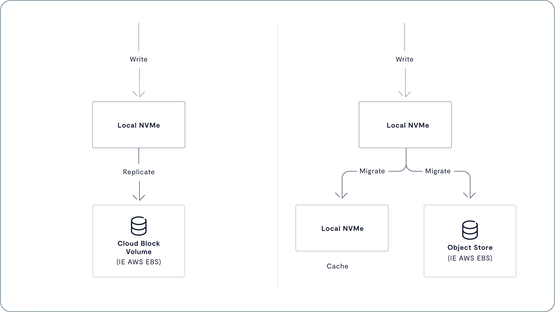
Cloud Instances and Global Clones
VAST cloud instances can also be used outside a full VAST DataSpace constellation using Global Clones. When the customer wants to run a disaster recovery drill or test a new version of software against their production data set they can run a VAST Cloud instance that mounts a clone of their production data set. The cloud instance will allow their test harnesses to have full access to the production data set while only fetching the small fraction the testing actually uses.
Any data written to a global clone is local to the cloud instance so any workflows that write valuable results to a cloud instance hosting a global clone should copy those results to a more resilient destination.
DataSpace Command
The VASTOS Management Service provides the management services to view, manage and control a single VAST Cluster, but the VAST Data Platform has many features that extend beyond the borders of a single cluster. DataSpace Command provides the management interfaces and the control plane to simplify managing these services.
Global Management
Legacy systems treat each NAS, database cluster, or SAN array as an independent management sphere. Whenever you want to replicate data between a pair of NAS appliances, you have to log into both systems, all too often, that requires entering commands into two separate terminal windows in the right order. Even worse, there’s no central configuration database to query, so the only way to find out which systems replicate specific folders is to examine the replication configuration on each system.
Once your VAST clusters are joined to the constellation of VAST clusters managed by DataSpace Commander, you can control VAST replication, Global Clones, and the Global Folders on all your VAST Clusters from one console. When the source cluster in your n-way replication fails and your secondary site takes over as the source, all the other clusters will now replicate from what was previously the secondary site.
DataSpace Command also provides a single dashboard to monitor and manage all of your VAST clusters. A single admin can easily view the health and performance of all, or a defined subset, of their VAST clusters and have a central console where they can respond to alerts from their whole VAST estate.
When VAST Admins see a cluster that needs attention in the DataSpace Command dashboard, they can simply double-click on the cluster they want to control and drill down into the console for that system with the same permissions, privileges, and roles as if they had logged in locally.
DataSpace Command for Cloud Control
DataSpace commander also provides the control plane for VAST Cloud instances allowing VAST admins to not only place Global Folders on VAST instances in their favorite cloud providers but also to instantiate and manage those cloud instances. Users can deploy and manage cloud instances from the DataSpace Command console, including setting policies for when those cloud instances should run to be managed by the VAST Data Engine.
The VAST DataEngine may decide that it should run a function, or a collection of functions, on public cloud compute resources because a peak in demand has overcommitted your primary data center or because spot prices have hit an all-time low on your favorite cloud provider or even because Amazon has the latest GPUs that are back-ordered for the next 17 months. When it makes that decision, it spins up a cloud instance before starting the function’s execution.
The VAST DataBase
Given the vertically integrated nature of The VAST DATA Platform, The VAST DataBase is more a convenient way to discuss the features of the VAST DATA Platform that access and manage structured data stored in tables than a software module in the traditional sense. Architecturally one could think of VAST SQL, the VAST dialect of the Structured Query Language, as just another protocol like SMB or S3 but in this section, we’ll take a more conventional view and talk about the VAST DataBase like it was an actual layer of compute resources and abstraction as in more conventional data platforms.
The VAST database uniquely combines an exabyte scale namespace for the natural data types (Images, video, LIDAR, genomes, and other rich, real-world data sources) and a tabular database to hold the catalog of expanding metadata about those objects that’s generated as data works it’s way through the deep learning pipeline, and that information is inferred. In 2024 you’ll be able to manage that pipeline through the VAST DataEngine, but that’s a story for another section.
Storing Data in Rows or Columns
Maintaining tabular data organized row-by-row is efficient for OLTP (Online Transaction Processing Systems), whose primary goal is to process transactions as quickly as possible. A typical transaction has to locate a handful of records, update some of them, and insert a new record or two. A row-organized database can perform these actions with a relatively small number of highly random I/Os.
Row-organized databases are less efficient at processing queries that collect data from many rows in a table. A query like “Show the average selling price for Blue Widgets by month for 2022” would have to read the entire sales transaction record (row) for every Blue Widget sale in 2022. If the table didn’t have indexes on date and item number, the query would have to read the whole table.
Since most queries are only interested in data from a small number of fields processing those queries requires reading a lot less data from data stored column by column than data stored row by row. Most current data analytics platforms transform data from a row-by-row organization to a columnar data organization where the data is stored column-by-column rather than row-by-row.
The open-source Apache ORC and Apache Parquet file formats used by many Data Lakes are columnar data files that store the values of a column across the members of a row-group. Tables in these Data Lakes are stored as hierarchical folders of Parquet files partitioned by one or two “key fields,” most typically partitioning by date to create monthly folders.
Today’s Data Lakes were designed by cloud companies like Google and Facebook, partly because they were among the first to collect petabytes of data they knew had aggregate value. Cloud companies design their solutions to run in the cloud, and the only affordable storage in the cloud is object storage, so file formats like ORC and Parquet and the higher level table formats like Apache Iceberg and Databrick’s Delta Lake were designed around the limitations of cloud object storage services like Amazon S3.
Since object storage services like S3 hold immutable objects, and there’s relatively high latency (10s to 100s of ms), the designers of today’s analytics systems designed those systems to minimize the number of I/Os they perform and to make those I/Os as sequential as possible. This begins with storing data column-by-column in large Parquet files and partitioning those files into folders based on column values. In addition, Parquet files also store the minimum and maximum values in each file’s footer.
When the system processes a query for all orders for more than 500 Blue Widgets it will first read the footers of all the Parquet files that hold the Quantity column. Since 500 is a large order, the maximum value in the footer of many files will be less than 500, which allows the query/database engine to avoid reading the actual data in those files.
Improved Reducibility
Column stores have one other significant advantage, the data in column stores compresses better than data stored row-by-row. The explanation for this is really very simple; they store similar data together. The values for any column in a table are constrained by that column’s type and real-world constraints. A simple example is that all the values of the zip code column in any table will be five-digit integers.
This data similarity between the values of a column, which is somewhat different from the similarity between data chunks used by similarity reduction, makes it easier to compress with both conventional dictionary and Huffman encoding techniques, and some file formats, including Parquet include compression via Snappy or GZIP. VAST systems have the additional advantage of data-aware compression algorithms that further optimize this type of data with techniques like run-length and delta encoding that store consecutive column values as differences.
VAST’s Columnar DataStore
As discussed in the introduction to VAST Table Elements above, The VAST DATA Platform stores Tables as a class of data Elements, the rough equivalent to the Elements that hold files/objects. Table Elements are stored in folders in the VAST cluster’s namespace and appear as files to client tools like ls or Windows Explorer.
The data in those Table Elements is stored in a tabular form inspired by the Parquet table format but is much finer-grained and managed by the same metadata that stores the Table within The VAST Element Store.
When data is written to The VAST DataBase, primarily through VAST SQL INSERT operation, that data is written to the VAST cluster row-by-row. The CNode receiving that INSERT writes the data into the SCM write buffers on two SCM SSDs just as it would for an NFS write or S3 PUT. This operation also makes the appropriate updates to the DataStore metadata.
As we saw in Transactionally Consistent, those metadata updates are fully ACI. Since the metadata updates are made after the data is written to persistent SCM SSDs, those same transactional semantics ensure that updates to VAST Tables are also fully consistent and ACID, like a relational database management system.
s we saw in the section on Table Elements, The VAST Data Platform stores tables in a tabular form inspired by the Parquet table format but much finer-grained and managed by the same metadata that stores the Table within The VAST Element Store. Each data chunk in the physical layer of The VAST DataStore holds the values for a column for a relatively small set of rows in the table.
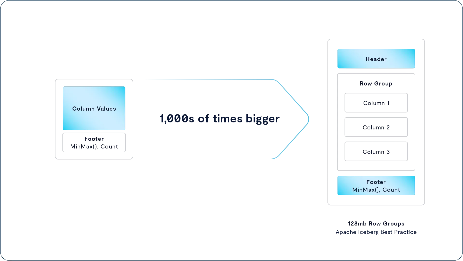
SQL was designed before columnar data stores; this isn’t an issue on queries since they specify columns, but INSERT and UPDATE operations will write data to the datastore row by row. In a VAST system, that data is immediately written to the SCM write buffer, where it is stored essentially as written, row by row. When the write buffer accumulates enough data to form a row group, those write buffers are flagged for migration to hyperscale flash., The same data migration process that organizes files into the 16-128 KB data chunks managed by the VAST DataStore’s physical layer transforms that data into columnar data chunks before writing to QLC.
Unlike Data Lakes and other datastores with immutable backends, the VAST Database allows users to INSERT and UPDATE just like a relational database should. The VAST Datastore is, as it has always been, a write-in-free space datastore, so the replacements created by an UPDATE will create new columnar data chunks with metadata linking to the new chunks in the background. Since VAST tables can contain billions of rows, each table can replace 100s of files across a complex partitioned hierarchy.
Even though the VAST Database stores data in blocks by columns, it can deliver the writability usually provided by row databases with small column-chunks and a storage back-end that performs small random I/Os and large sequential reads. Using small column blocks also allows queries to run against a table via multiple dimensions like date and location without partitioning the data by each, creating multiple copies. The penalty for reading a 32 KB column block, because it contains 1 value in range, is much smaller than when 1 value between a footer’s min and max meant reading a 1GB Parquet file.
The VAST Database isn’t just a replacement for the Data Lakes full of Parquet and ORC files. It’s a full database supporting relational/transactional applications with indexes, UPDATES, INSERTs, and other functions alien to immutable data stores. While the latest table formats allow users to rename columns or save a point-in-time snapshot on a table stored in an immutable object store, they perform their magic with layers of metadata redirection that interconnect multiple files and add both I/O and delays as queries follow complex chains to locate the data they need through multiple layers of abstraction.
Since the VAST Database has a single, integrated set of metadata for its tables, from schema directly to data blocks, there’s no need for additional external metadata layers in additional files or metabase databases. Table snapshots are handled with the same zero-footprint snaptime mechanism that provides file system snapshots, and since the VAST DataStore is a fully writable, ACID, repository operations like renames, column add, and even column deletions are actually performed, not simulated by layers of metadata manifests.
Accessing the VAST DataBase
The short answer to how you access VAST tables is that you access them just as you would any other tabular database via SQL (Structured Query Language), the lingua franca of tabular data. For the most direct access to VAST Tables, applications can send a CNode queries in VAST SQL, the VAST dialect of Structured Query Language.
SQL is a complex language, and unfortunately, ANSI SQL has always been one of those standards where even compliant solutions are different enough that many applications must be dialect-specific, so we knew just introducing yet another SQL dialect wouldn’t make life easy for our customers.
We’re making it easy for customers to move their data into the VAST DataBase without re-writing or even testing all their applications by providing plug-ins for popular SQL query engines and data platforms. Today we provide plug-ins for Apache Spark, including the DataBricks platform, Vertica, Dremio, and Trino, including Snowflake. These plug-ins allow those platforms to push functions, like filtering, down to the VAST Database, allowing the VAST Data Platform to return the results of the pushed-down predicates so the Spark or Trino server cluster has to process orders of magnitude less data.

Database File Ingest
Users can, of course, create new tables directly via SQL, and many applications will simply use SQL as a data definition language to create their databases; but running several PB of analytics data through your compute cluster is a very expensive way to copy a petabyte or two of existing data from Parquet files into VAST Database tables, especially if those Parquet files are already stored in a VAST S3 bucket holding a data lake.
The easy way to ingest that data is to simply define a folder/bucket as containing a specified table through the VAST API or GUI. The system will then ingest any Parquet table, or Iceberg data warehouse stored in that folder into VAST Database tables. Once all the data is stored as a single table element, you can delete the original files and folders along with all the work of managing file and folder sizes to accommodate storage limitations.
Both Analytical and Transactional
While some smaller-scale database solutions have provided decent OLAP (Online Analytics Processing) query processing performance while maintaining the ACID consistency required to reliably process transactions, those solutions can’t handle more than a few TB of data. Large-scale analytics solutions either can’t process transactions at all or can only process transactions at a modest rate against a single table.
The VAST DataBase is structured to support high performance for both transactional updates and analytical queries. We’ve already looked at how the VAST DataBase stores newly written database rows to SCM SSDs and transfigures that data into small, columnar (16-128 KB average) data chunks to optimize query performance.
Those small column chunks are how the VAST DataBase can also process transactions without an inordinate amount of overhead. When an UPDATE modifies some existing data in a table, that data can be in one of two places. If the data being updated is the quantity on hand for the latest Taylor Swift album the day it drops, that UPDATE is updating a record that’s still in the SCM write buffer. In that case, the system records the new data and updates the table metadata to point to the latest version.
If the data being updated has already been written to column chunks on hyperscale flash SSDs, the system reads the chunk that holds the data being updated and writes a new version of that chunk into the write buffer. A 32 KB column chunk is pretty much the same size as a database page on a relational database system allowing the VAST platform to run applications that need OLTP-level transactions, even across multiple tables.
Merging Content and Context with the VAST Catalog
Having a relational database for context (Metadata, indexes, Etc.) and an organized file/object store for content is a pattern that appears across a wide range of applications, not just Data Lakes and Artificial Intelligence Feature Stores. The dual datastore model drives PACS systems for medical imaging, Media Access Management systems (MAMs), enterprise document management systems, and countless other data management systems that track some portion of the context of media from documents and spreadsheets to JPEG images and video of Hank Aaron’s 715th home run in relational databases.
Frankly, the dual datastore model works decently for Feature Stores and Data Lakes because the users of those systems only access their contents through tools that also can manage, or at least access, the metadata store. When we move into use cases where users have more direct access to the contents, the fragility of having two loosely coupled data stores raises its ugly head.
Suppose users mount the content repository, which they must to use desktop applications like video or photo editors. In that case, those users can delete, rename, move, or edit files without updating the metadata store. At best, the system does a scan of the content repository overnight and sends a report with the broken links and files with newer modified dates so an administrator can fix the broken links and make the two datasets consistent again. In the worst case, no one discovers broken links until years later when no one remembers where the files were moved to.
Enter The Catalog
At its core, the VAST Catalog is simply the most obvious use of the VAST Database. The VAST Catalog makes the VAST Element Store metadata accessible not just as a nested series of files (folders) holding metadata about other files accessed folder by folder via NFS or SMB but as a VAST Table. With the catalog finding all the files that have changed since the last scan at midnight is a simple SQL query:
SELECT path,name, size for MTime>midnight
The VAST system will process that query, and a few seconds later, a list of the files that have changed since midnight and their sizes will be returned.
Without the catalog, our administrator friend, or more accurately, their workstation, will have to search the filesystem, loading each folder’s contents to both see if there are any new files and, more significantly, if there are any additional folders to search. These file system walks are notoriously slow, taking days, if not weeks, for file systems with billions of files because file system metadata is organized to provide fast access to a file, much more than it is for search.
This problem first became critical when users tried to run their nightly backups, and the file system scans started taking so long that incremental backups never completed in their window because they never finished searching the file system.
The VAST Element Store generates the catalog table from a periodic snapshot of the cluster’s namespace; like all VAST snapshots, the minimum granularity is 15 seconds, but generating a new catalog table every 15 seconds for a namespace of billions of elements is probably more work than it’s worth. More typically, the Catalog is updated every 15 minutes to an hour.
Insert .CSV segment of 5-8 files and selected fields
Handle,ParentPath,Name,Size,Ctime,MTime,ACL
Since the Catalog is a VAST Table, like any other VAST Table, users can access it through VAST SQL or the VAST Spark and Trino plug-ins, but since not everyone who needs access to the Catalog is a data scientist, we’ve also provided tools a little more accessible to system administrators.
As you can see in the screenshot above, administrators can build queries through the VAST GUI and receive the results in JSON. Over time admins will also be able to export query results to additional file formats, including CSV.
With the Element Store metadata available as a table, VAST customers can easily query that table for everything from auditing that users haven’t expanded the ACLs on sensitive datastores to reporting capacity utilization by group or project.
Extensive and Extendable
As nice as having the Element Store metadata accessible as a table is, the VAST catalog is more than that because the Catalog metadata is more extensive than the basic metadata POSIX file systems provide and almost infinitely extensible. In the first case, since The VAST Element Store is both a file system and an object store, the VAST Catalog includes all the metadata defined by NFS, SMB, or S3, including S3 object metadata and extended tags.
Customers can use simple queries to the Catalog table to verify their secure data’s ACLs limit access the way they should and report consumption for bill-back or simply to shame users into cleaning up their scratch space. But things get really interesting when VAST customers start combining the basic metadata the VAST Element Store provides with all the other context sources about their files.
Those other context sources include the metadata embedded in media and document files and the metadata created at each stage of your workflow, from columns for actors and directors attached to video files to full-text indexes and DLP system sensitivity evaluation.
Before VAST, customers would collect this data in a relational database through a Media Asset Management or Enterprise Document Management system. That database would connect the context it held to the content in the associated file system with links, typically URLS or UNCs, to the file’s location. If files are renamed, copied, or moved outside the MAM or EDM, those become broken links.
Inseparable Context
The problem is that old-school content management systems were really two independent systems loosely coupled not by some immutable attribute of each file it manages but by the file’s location as a URL or UNC. When VAST customers add metadata columns, or tables, to the VAST Catalog, they store data in tables keyed off the unique Element handle assigned to each Element in the VAST Element store. Keying off this unique handle means that any extended metadata is tightly coupled to the Element itself, not to the Element’s location, and will remain attached to the Element even when the file is moved from one folder to another or cloned via a server-side copy method like ODX.
Catalog Snapshots Add The Dimension of Time
The VAST Datastore uses snapshots to create a consistent point-in time view of the VAST Element Store to protect the VAST Catalog’s tables from but that’s not where the connection between The VAST Catalog and snapshots end. Catalog tables, like snapshots have a retention period and a query can specify which snapshot(s) the query should run against.
The VAST database will not support joins or queries across multiple tables in the initial releases so users will have to use a query engine like Trino to process queries across multiple tables, or use VAST Uplink with its AI powered prediction engine to project capacity consumption. The option to generate a change-list with each updated Catalog is planned for release shortly after.
The VAST DataEngine
The VAST DataEngine, which will start shipping in 2024, is where computation really joins the VAST Data Platform. This section presents a preview of the capabilities the VAST DataEngine will deliver.
The VAST DataEngine provides the execution and orchestration intelligence to manage and execute the function pipelines that let data scientists and deep learning practitioners scrape, transform, train, infer, and otherwise derive value from the files/objects and tables the VAST Data Platform holds without worrying about where, how, or possibly when, those functions are executed. The VAST DataEngine automatically optimizes these pipelines to minimize cost, execution time, and/or system utilization to deliver a serverless execution environment across multiple on-premises and cloud locations.
At the most basic level, the VAST DataEngine is analogous to an operating system’s supervisor or the supervisor/state machine at the core of every storage system, including the VAST DATA Platform. Storage systems are constantly reacting to event triggers like SSDs failing and the arrival of user requests. These events trigger functions like erasure-code rebuilds and data reduction. The supervisor assigns the threads of the rebuild or a query across its available resources.
The big difference is that the VAST DataEngine takes a much broader view, managing not only the resources of a single server or even a single cluster in a single location but all the resources you make available to it. The VAST DataEngine turns all the computing resources across all of your data centers, and those public cloud resources you give it access to, into an integrated thinking machine that takes data in and delivers valuable insights. Let’s take a look at how.
Event Triggers and Functions
The heart of the VAST DataEngine are two new concepts so central to the DataEngine’s operation that we’ve defined new Element types in the VAST Element Store for them, Event triggers, and functions. Triggers define the conditions that require an action of some kind, and functions define the actions to be taken.
Since Triggers and Functions are Elements, they can be created and edited as files in the appropriate formats. The VAST DataEngine includes a Python toolkit for building functions, further demonstrating the plasticity of data, metadata, and code in the VAST Data Platform.
Event Triggers
As we’ve stated, event triggers define the conditions that should cause the system to act. Those conditions are based not just on the event itself but can also include filters and rules that define which objects should trigger functions, how those functions should be executed, and where they should output their results. Some of the basic conditions VAST Customers can define as Event Triggers are:
CRUD (Create, Read, Update, Delete) events in the VAST Element Store. For example, any file of the type JPG created in the /Photos folder will trigger the built-in metadata scraping function.
Row CRUD in VAST Tables. A new row in the specified table. Since The VAST DataEngine stores Kafka topics as VAST Tables, new entries to a Kafka topic can also serve as a trigger
Any of the 1000s of analytics counters in the VAST cluster
The completion of a previous function
Event trigger rules provide fine-grained control over whether the trigger activates per event, based on folders in the namespace, catalog metadata, rates, and other filters. The event trigger rules also allow users to set execution preferences (run this function fastest vs. cheapest). When conditions fit all the event trigger parameters, the system will execute the specified function(s).
Functions
Functions are the definitions of the software functions and microservices the system can perform when the conditions of an event trigger are met. Each Function Element defines the execution requirements of a given function, say a GPU-powered inference engine performing facial recognition. This would include hardware and location dependencies for functions orchestrated by the VAST DataEngine, or simply the execution method for functions performed by the cloud or other services outside the VAST DataEngine’s compute environment.
Since the global workflow optimization engine, described below, will choose which function to perform a task based on cost, The VAST DataEngine also keeps information on the cost, CPU resources, and execution time of each function each time it’s run, and uses these factors to run functions in the optimal location each time.
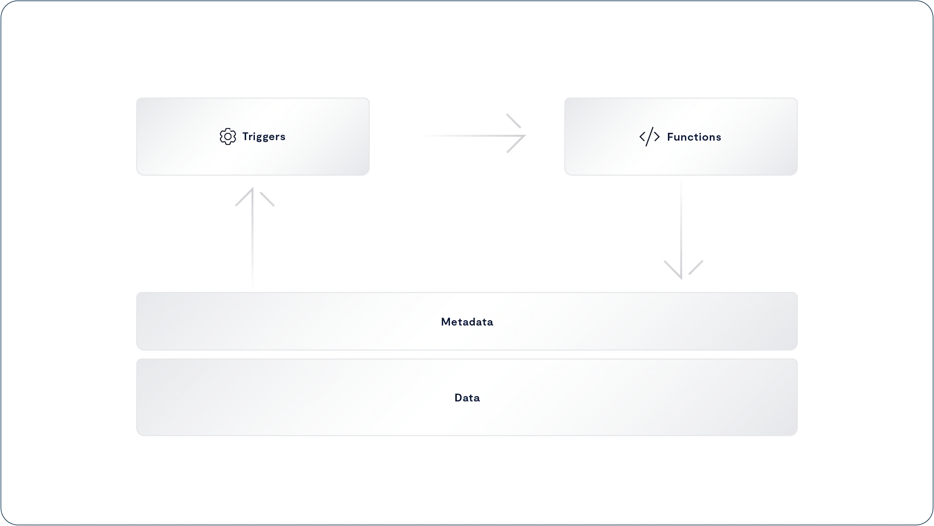
The VAST Computing Environment
The VAST Computing Environment upon which the VAST DataEngine operates breaks down into two major pieces. First is a global workload optimizer that responds to event triggers, figures out the best place to run each instance of each function, and calls the services that perform those functions, from scraping metadata to matching millions of genome segments. The second is the execution and orchestration engine that manages the containers that deliver the function’s services.
The Global Workflow Optimization Engine
The global workflow optimization engine goes beyond a mere task or job scheduler, providing toolkits that let you assemble the event triggers and functions we discussed above into declarative workflows with rules that define the causes, effects, and interactions between all those system Elements.
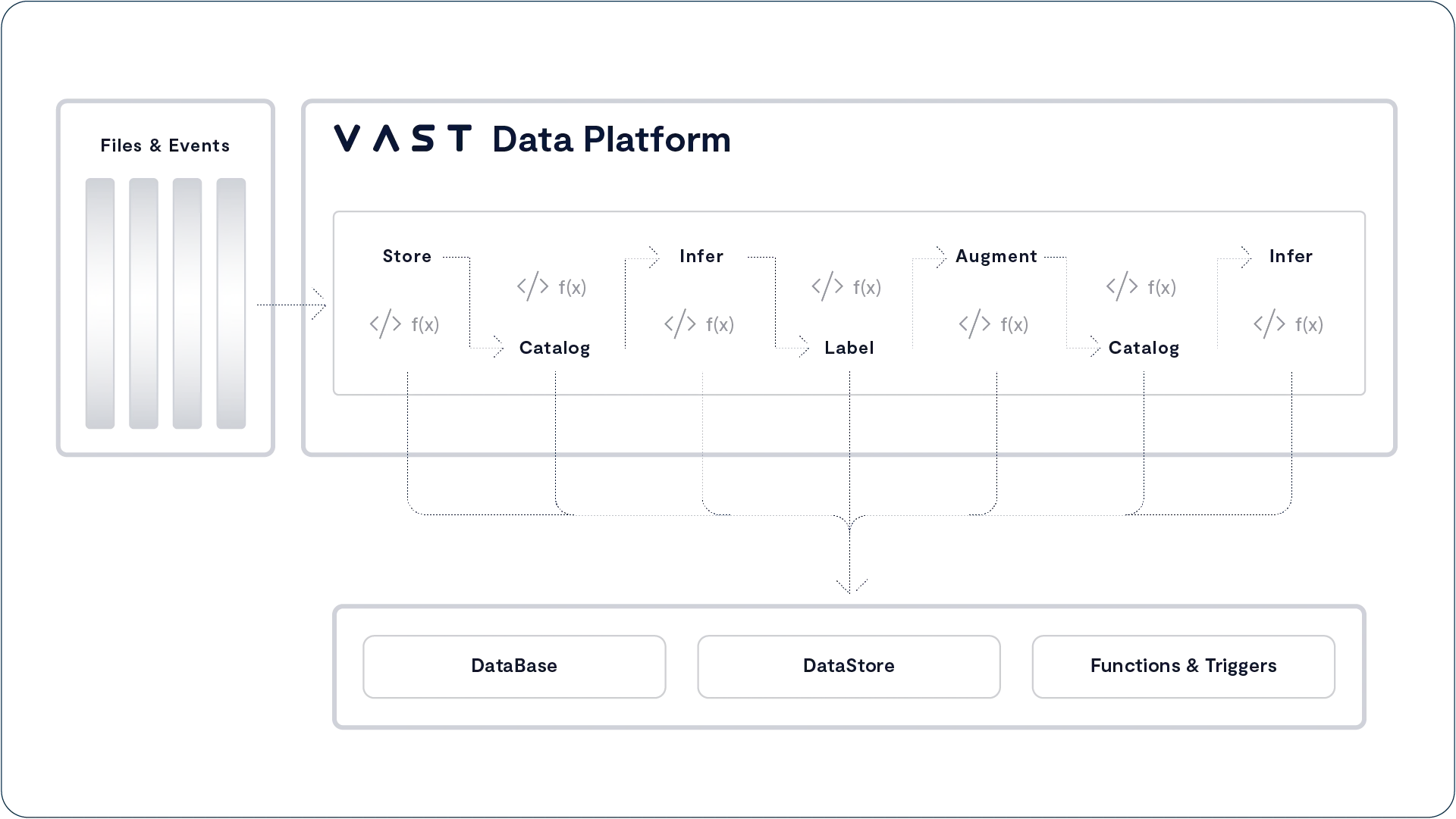
A workflow may start by scraping the embedded metadata out of the incoming files into The VAST Catalog. An event trigger may then detect that a subset of those files are, based on that photographs taken in Las Vegas over the New Year’s weekend and cause an inexpensive inference function to run on those files and identify a smaller subset of images that include the image of a red car, those files are subjected to more extensive processing to ultimately return the license plate number for a hit-and-run.
Since Event Triggers can include rates, counts, and time the system can process both event-driven stages that trigger functions immediately on each event and data-driven stages that allow data to batch to some degree before spinning up the function to process them.
Workloads can define multiple options for any stage in the workload. A workflow could, for example, provide three options for transcoding video, one function that uses on-premises GPU resources, a second function that uses CPU resources but consumes more resources and runs slower, and a third that uses a public cloud transcoding service, The optimization engine will choose which function to run, and where to run it based on the conditions at the time and the service optimizations, primarily execution time SLA and costs, you selected.
Process Functions Worldwide
The VAST DataEngine maintains an internal database of the resources it manages from the various VAST clusters in the VAST DataSpace, and the folders they share to the computing resources (CPUs, GPUs, Memory, Etc) available to run functions in each data center, the networks connecting the various locations and much more. When planning a workflow, the optimization engine will orchestrate functions to optimize each workflow stage for performance or cost as the user dictates.
Circumventing Data Gravity
Dave McCrory coined the term data gravity to describe how massive datasets develop an attraction for applications the same way massive objects have a gravitational attraction for each other. Once an organization develops a massive dataset, that dataset attracts applications that create additional data, which in turn attract additional applications. The organization becomes trapped in its headquarters data center or selected public cloud region.
Just as the pull of real-world gravity is a function of the mass of the objects attracting each other, data gravity is a function of the mass, or more properly, the size of the overall dataset. The more data, and the more types of data, stored in one place, the more attractive that place becomes as a home to run the applications that will process that data.
The VAST DataEngine circumvents data gravity by shielding applications from the mass of the entire collected dataset, leaving each function only attracted by the data it accesses. The concept of data gravity presupposes that since which data each application will access is unpredictable, even applications that only access small subsets of the entire dataset are drawn in by the gravity of the dataset as a whole.
Since The VAST DataSpace only transfers the data that’s being accessed and keeps that data local in the very large cache of a VAST cluster, the VAST DataEngine learns where data is and how to move the execution of functions to where the data they access has been accessed before.
The VAST DataEngine performs a best fit against the rules defined in a workflow to:
Perform functions close to a replica of the data they access when sufficient resources are available to meet the workflow SLA.
Move only active data to compute using the VAST DataSpace
When specialized compute like GPUs is required/fastest/cheapest
When compute resources are unbalanced moving functions to locations with idle resources can reduce the total execution time and increase the total work
Cloud bursting to provide elastic computing capacity
To leverage low spot pricing for long-lived workflows
The VAST Execution Environment
The VAST Execution Environment provides the computing resources for the VAST Data Platform to perform its work, and for the VAST DataEngine to process user functions. The VAST Data Platform can orchestrate all of its computing functions across a single pool of servers optimizing their utilization.
An organization building workflows from legacy tools will have to stand up multiple clusters:
The Object Store to hold their Iceberg and Parquet files
A Cluster to run their database management/query engine (Spark, Trino, Dremio, Etc.)
A Kubernetes pod to run the containers that run the training, inference, transformation and other user tasks
Scheduler/orchestrator, message broker and other "glue" functions
Each of those clusters needs physical resources, and operational resources to maintain and update them. Since IT operators typically size each cluster for their expected peak utilization, and those peaks never all happen at the same time, multiple clusters lead to reduced utilization. Operators can’t easily spin up Trino containers in the Kubernetes cluster because the Trino servers need local SSDs for cache and can’t run other containers on the Trino servers so they add an extra server or two to both pools for headroom.
VAST has always developed our software using Linux containers, we explain elsewhere in this paper the benefits containers provide as a software distribution method because before the Vast DataEngine VAST clusters ran all the code for a CNode or DNode in a single container, plus 1 container for the cluster’s VMS management service. There are multiple service modules within each container of course but pre-VAST DataEngine VAST clusters don’t orchestrate ephemeral containers to provide a
The VAST Execution Environment uses The VAST DataEngine as the control plane orchestrator of Kubernetes pod(s) that run VAST containers along side customer provided containers that train deep learning models, infer the photos that have faces, and recognize who’s face it is for that all important social media tag.
This allows the VAST Execution Environment to optimize a much broader set of compute functions across a singe pool of resources than conventional data platforms achieving higher utilization and therefore lower cost per function.
While we call it a single pool of resources you shouldn’t think that means a heterogeneous pool of resources. Functions can have hardware requirements from 512 GB of DRAM to a GPU compatible with a specific library, VAST containers require direct access to the cluster’s storage fabric, Etc.
The VAST Execution Environment orchestrates user provided containers along with the VAST containers, that provide all the services of the VAST Data Platform from rebuilding erasure code data after an SSD failure to processing SQL queries and running the DataEngine’s optimization engine itself: VAST containers will also run functions users create with VAST’s Python toolkit in an AWS Lambda-like environment.
A Kafka-Compatible Event Broker
As a data platform company it would be easy to build a data-driven execution engine that used CRUD events to the VAST DataStore to trigger functions but that would force VAST Customers, and the developers of the microservices that those customers call as functions to adapt their pipelines to a data-driven model. The problem with that approach is that it violates one of VAST’s most basic design tenets, to keep things simple for our customers by supporting standard protocols, interfaces and APIs.
In this case the standard APIs are those from Apache Kafka the open-source event broker. Kafka is the most popular broker for event-driven, sometimes called streams driven communications between microservices or other applications. A Kafka cluster provides the infrastructure that allows providers to write messages to one or more persistent, replayable logs, called topics. Consumers can subscribe to those topics and read those messages. The messages in a Topic can have a defined schema, or simply be in a message format agreed to by the producer and consumer.
The VAST DataEngine accepts Kafka APIs storing each topic as a Table in the VAST DataStore and each message written by to the DataEngine through the Kafka Producer API as a row/record in that table. These messages will be available through the Kafka Consumer and Kafka Streams APIs and since a Kafka Producer writing a new message is an update operation, messages can trigger functions directly.
VAST systems don’t require administrators to partition Kafka topics for performance or reliability which means that The VAST DataEngine can maintain write order integrity across an entire topic not just partition by partition like Apache Kafka.
Since Kafka is intended as a message broker it is designed for small messages, generally 1 MB or less. When users want to send an event to another system and that event includes rich media over 1 MB in size Apache Kafka has required them to either include a URL or other reference to a file on a second storage system or encode the payload in a large number of Kafka messages, a very complex operation that will consume a lot of Kafka cluster and network resources.
The problem with reference-based messaging is a problem that has plagued the internet since time immemorial (or at least 1996) broken links. If the Kafka server and external storage get out of sync, bad things happen Since The VAST Data Platform is a single system supporting both the Kafka messages and unstructured data via S3 VAST users can embed URL references in their Kafka messages with no fear of consistency issues let alone broken links.
Kafka quotas are supported as QoS limits on the VAST Table Element that makes up the topic and last but certainly not least since Kafka topics are VAST tables they can be queried and reported on like any other tables through the VAST DataBase APIs.
Built-In Functions
Most of the work of inferring value from unstructured data on the VAST DataEngine will be performed by functions provided or created by VAST customers and orchestrated by the VAST DataEngine. In some cases, some functions can be performed more effectively by the data platform, and The VAST Data Platform will include several built-in functions, a few of which are described below.
Metadata Scraping
One of the best sources of information about files is metadata embedded in the files themselves. File formats from Microsoft Office documents to MP4 videos and JPEG photos all include embedded metadata from the geolocation where the photo was taken to the date the file was actually created, a very different thing from the POSIX CTIME attribute, or VAST Catalog column that records when the file was first created in this namespace.
Historically the problem with embedded metadata is that this metadata is essentially unsearchable. Conventional storage systems simply can’t deliver all the photos in their repositories taken 12/30/2022-1/2/2023 in Las Vegas without an application opening every file to examine that embedded metadata. That’s going to create a huge amount of storage traffic. Even worse, the scraping application needs to know the format of every file type from which it needs to scrape metadata.
The VAST DataEngine’s built-in metadata scraper function allows VAST customers to import embedded metadata from a wide variety of file types. The system includes metadata schema for several common file types, including the EXIF metadata embedded in JPEGs, and a Python toolkit for importing metadata from other data types.
When you want to index the embedded metadata for a photo repository, all you have to do is create an event trigger for new files of the type JPEG in the appropriate folder that calls the metadata scraping function. You can also specify the table, or Kafka topic, you want the metadata scraped into, and filters on which columns you want to populate. Once that event trigger is enabled each new JPEG will automatically have its metadata scraped into a VAST Table, keyed to the file/object’s unique handle to make this metadata inseparable from the file it describes.
PII Detection
Regulatory frameworks worldwide are constantly increasing organizations' responsibilities to protect their stakeholder’s Personally Identifiable Information (PII) from Social Security or National Insurance numbers to addresses and telephone numbers. Unfortunately, this information is also critical to many business processes. It may be included in Elements, like contact lists, which may circulate within an organization but should not be shared with outsiders.
To ensure that PII doesn’t leak through public-facing folders or, more likely, S3 buckets, VAST customers can apply an event trigger for file-create operations in the specified folder that calls the PII Detection function. When users create files, the PII Detection function will scan the specified files looking for data formatted 999-99-9999 or that otherwise looks like the PII you specified. If it finds such PII, the PII Detection function returns true, which triggers another event.
That OnPII_Detected event can trigger any additional functions the customer desires. These could easily include locking the file, sending the objects URI to a Kafka Topic so a third-party DLP solution can sanitize the file, and packaging the audit information for the user who exported PII and emailing it to the CISO.
Ransomware Detection
The ransomware detection function leverages the anomaly detection engine built into VAST’s Uplink storage management service specifically to detect ransomware infiltration and attacks by their behavior.
When, for example, a small number of users are writing to a large number of files in folders where that hasn’t happened before or the data in a folder has a sudden decrease in its reducibility, the ransomware detection function will trigger one or more additional events that can, in turn, run additional functions to preserve data by taking a snapshot of effected folders, extending the retention period for existing snapshots and/or disconnect the offending user in addition to paging the CISO.
Training Augmentations
When training image recognition and computer vision models, AI practitioners have to prevent the model from overfitting, that is, learning that some specific feature in the small number of cat photos their model is being trained on infers “catness” instead of general attributes like fluffiness, and whiskers. The training augmentation functions perform basic transformations like flipping and blurring images. Introducing these transformed images into the training set reduces overfitting and improves the model’s ability to concentrate on the important things.
Managing The Platform
Operating legacy data platforms at scale has required extensive engineering in multiple disciplines. A multipetabyte object store needs to be deployed and managed to hold the data lake of Parquet, image and other files, including periodic migrations between hardware/software generations. The platform’s data management layers typically run a metabase on a relational database like MySQL, which needs another cluster for the database server processes and a durable storage system to hold the database. Finally the query execution engine like Vertica, Spark or Trino runs on another compute cluster and the servers in that cluster have local SSD caches.
Managing performance, or scaling a platform like that requires careful planning of the storage, compute, memory and network requirements at each layer, and balancing the demands of each. Customers who believe the myth that the only old-fashioned HPC parallel file systems can provide the performance GPU computing demands (see NFS Now For Speed to disprove this myth) have to maintain expertise in yet another complex system.
Compare that to the VAST DataPlatform where instead of three or four separate clusters (Object Storage, metabase, query engine, Etc.) to manage, and keep in sync, there’s a single cluster of CNodes providing access to exabytes of structured and unstructured data, and all the services that manage them. The VAST DataEngine provides a single environment that stores, catalogs, indexes and runs your inference functions across all your structured and unstructured data on a single pool of resources.
API-First Design
Twenty-first century data centers should be managed not by a high priesthood of CLI bashers who are charged with maintaining farms of data storage silos, but by orchestration platforms that manage individual devices not through a CLI but through more structured, consistent, and accessible application program interfaces (APIs).
VMS is built with an API-first design ethos. All VMS management functions on the Cluster, from creating NFS exports, to expanding the cluster are exposed through a RESTful API. To take the complexity out of learning how to work with APIs and writing according to various programming languages, the VMS publishes APIs via Swagger. For the uninitiated, Swagger is an open-source API-abstraction that publishes easy tools to build, document and consume RESTful web services.
While the VMS also provides a GUI (details below) and a traditional CLI, VMS’s API-first design means the GUI and CLI consume the RESTful API rather than controlling the system directly. This approach ensures that API calls are sufficiently tested and that all system functions will always be available through the RESTful API. Systems with CLI- or GUI-first design philosophies can often treat their RESTful APIs as second-class citizens.
A Modern GUI
While a RESTful API simplifies automating common tasks, GUIs remain the management interface of choice for customers who want a quick and simple view of system operations.
A good dashboard allows mere mortals to quickly understand the health of their storage system in seconds and provides a full-featured GUI that makes it easy to perform simple tasks while also allowing more curious parties to drill down into the data that feeds that dashboard.
The VAST web GUI is implemented entirely in HTML5 and does not require Java, Adobe flash, browser plug-ins or any other client software. Administrators can manage their VAST Clusters from any modern browser.
Viewing Analytics Data
The VAST GUI’s main dashboard provides a system’s administrator or another user who has been given RBAC permissions, a quick snapshot of the system’s health. Detailed analytics are also provided to understand what’s happening both at the system level and at the application level.
VMS’s User Activity screen allows administrators to reverse-engineer application performance issues by helping them understand the users, exports and clients that are interacting with the system, and the levels of traffic they’re creating. User Activity provides the ability to monitor any of the users of the system in real time, not just the top 10 “bad actors”.
For historical data analysis, VAST Analytics dashboard provides administrators with a rich set of metrics to monitor everything from latency, IOPS, throughput, capacity and more – all the way to the component level.
Administrators can even create and save customized dashboards by combining any number of metrics they find useful in order to determine event correlations.
VASTOS Cluster Management
Just as VAST Datastore was designed to redefine flash economics, VAST Clusters have been equally designed to minimize the cost of scale-out system operation by simplifying the system’s full lifecycle of operation – ranging from day-to-day management tasks such as creating NFS Exports and quotas… all the way to performing automated, non-destructive updates and expanding the cluster online.
The VASTOS Management Service
The VASTOS Management Service (VMS) is responsible for all the system and cluster management operations across a VAST Cluster. VMS is a highly available service that runs as a Linux container in a VAST Cluster. VMS functions include:
Exposing the VAST Cluster’s RESTful API
Serving the cluster GUI and CLI
Collecting metrics from the servers and enclosures in the cluster
Reporting metrics to user
Reporting metrics to VAST Uplink
Automating and managing cluster functions
Software updates
System expansion
Authentication
VAST Clusters can authenticate users, and groups, using NIS, LDAP and/or Active Directory including support for RFC2307 and RFC2307bis for Active Directory/LDAP to UID/GID mapping.
To support users who are members of more than the 16 groups that NFS clients support, VAST systems query the LDAP/Active directory service directly for group memberships including RFC2307bis nested groups.
VMS Resilience
VMS runs in a container that is independent from the container that runs the VAST Server and Protocol Manager processes. The VMS container only runs management processes that take instructions from the users, and exchanges data with the VAST Servers and Enclosures in the cluster. All VMS operations are out-of-band from the VAST Protocol Manager to ensure consistent I/O performance.
While VMS today runs on a single server, it is also designed to be highly available. Should a server running VMS go off-line, the surviving servers will detect that it isn’t responding and first verify it is really dead before holding an election to assign a new host for the VMS container – at which point the new host will then spawn a new VMS process. Since all the management service state, just like Element Store state, is stored in the persistent Storage Class Memory, VMS takes over right where it left off when it ran on the failed host.
VMS Analytics
VMS polls all the systems in VAST Cluster every 10 seconds, collecting hundreds of performance, capacity, and system health metrics at each interval. These metrics are stored in the VMS database where they’re used as the source for the VAST GUI’s dashboard and other in-depth analytics which we’ll examine in more detail below.
The system allows an administrator to examine analytics data over the past year without consuming an unreasonable amount of space, by consolidating samples as they age reducing granularity from a sample every 10 seconds to a sample once an hour for data over 30 days old.
VAST Uplink
VAST’s Remote Call Home Service
In addition to saving those hundreds of different types of system metrics to their local databases, VAST clusters also send encrypted and anonymized analytics data to VAST Uplink, a proactive remote monitoring service managed by the VAST Customer Support team. VAST Uplink is available on an opt-in basis. Customers with strong security mandates are not required to run Uplink to receive VAST support.
VAST’s support and engineering teams use this platform to analyze and support many aspects of its global installed base, including:
System health – in many cases the VAST Support team will know of system events before customer administrators do
Monitor performance to ensure that VAST systems deliver the appropriate levels of service quality and expected throughput, IOPS, latency
Publish non-disruptive SW updates to VAST’s global installed base
Track the benefits of Similarity-Based Data Reduction across different customers to develop trend lines around use cases
and more.
Uplink also provides VAST’s R&D team invaluable insight into how customers actually use VAST Datastore Clusters, so we can concentrate our engineering toward efforts that will have the greatest positive impact on customers.
Non-Disruptive Cluster Upgrades
Too many storage technologies today still have to be shut down to update their software. As a result, storage administrators (who perform these outages during off-hours and weekends) will optimize their work/life schedule by architecting storage estates around the downtime events that their systems impose upon them. The result is the use of many, smaller systems, to limit the scale of the outages they have to endure. Another way administrators avoid the perils of upgrade-driven storage downtime is to delay performing system updates, which has the unfortunate side-effect of potentially exposing systems to vulnerabilities and fixes that their vendors have solved for in more current branches of code.
VAST Data believes that disruptive updates are antithetical to the whole concept of VAST Datastore. A multi-purpose, highly scalable storage system has to be universally and continually available through routine maintenance events such as system updates.
The Cluster upgrade process is completely automated… when a user specifies the update package to be installed, VMS does the rest. The statelessness of the VAST Servers also plays an outsized role in making cluster updates simple – as the state of the system does not need to be taken offline in order to update any one computer. To perform the upgrade, VMS selects a VAST Server in the cluster, fails the Server’s VIP (Virtual IP Addresses) over to other VAST Servers in the cluster and then updates the VAST Server container and the VASTOS Linux image (in the case of an OS update) on the host. VMS then repeats this process, transferring VIPs back to the updated servers as they reboot until all the VAST Servers in the cluster are updated.
Updating the VAST Enclosure follows a similar process. VMS instructs the VAST Enclosure to reprogram an enclosure’s PCIe switches to connect all the SSDs to one DNode, and all the VAST Servers then connect to those SSDs through the still-online DNode. Once the failover has completed – VMS will update the DNode’s software and reset the enclosure to get it back online in an HA pair.
Expansion
The ability to scale storage performance, via VAST Servers, independently from Enclosure capacity is one of the key advantages of the DASE architecture. Users can add VAST Servers and/or VAST Enclosures to a cluster at any time.
As we saw in the Asymmetric Scaling section, VAST clusters can be composed of heterogeneous infrastructure as a system scales and evolves over time. VAST Servers using different generations (different generations or makes of CPUs, different core counts) with different VAST Enclosures (differing numbers and sizes of SSDs) can all be members of the same cluster without imposing any boundaries around datasets or introducing performance variance.
When VAST Servers are added to a cluster or Server Pool, they’re assigned a subset of the cluster’s VIPs and immediately start processing requests from the clients along those VIPs, thus boosting system performance. Users can orchestrate the process of adding VAST Servers to their cluster to accommodate expected short-term demand, such as during a periodic data load and releasing the hosts to some other use at the end of that peak demand period thanks to the containerized packaging of VAST software.
When enclosures are added to a VAST Cluster, the system immediately starts using the new Storage Class Memory and hyperscale flash to store new user data, and metadata, providing a linear boost to the cluster’s performance.
I/O and pre-existing data are rebalanced across the expanded capacity of the system:
Writes are immediately spread across the entirety of the expanded pool of Storage Class Memory, so write performance automatically scales with the new resource
Newly written data will be striped more widely across the expanded pool of hyperscale flash because of VAST’s write-in-free-space approach to data placement, making subsequent reads to this data equally well-balanced
Pre-existing data will remain in the SSDs it was originally written to and will, over time, be progressively restriped when the system performs routine garbage collection. VAST Systems don’t aggressively re-balance data at rest on the senior enclosures because that would cause write-amplification and impact performance without any real benefit. Data on the existing enclosures is already wide striped across at least 44, and most commonly 100s of SSDs there’s limited advantage to striping data even wider.
Batch-Delete: The .Trash Folder
Many user workflows include cleanup stages that delete a working directory and its contents. VAST’s batch-delete feature offloads this process from the NFS client to the VAST system, which both allows workflows to proceed without waiting and reduces the load on both the customer’s compute servers and the VAST system.
Deleting large numbers of files via RM -rf /foo/bar or some equivalent can take a considerable amount of time as RM command walks the directory tree with a single thread looking up and deleting files one by one.
To delete a folder and its contents, a user moves the folder to be deleted to a special .trash folder in the root of the folder’s NFS export. Once the folder has been moved, the VAST system deletes its contents in the background.
Moving a folder is a single NFS rename call, relieving the client from walking the directory tree and deleting the files one by one.
Since the actual deletion occurs in the background, the system’s free space available won’t reflect the space occupied by the deleted files for some minutes after they’re moved to the .trash folder.
Details:
The .trash folder can be enabled or disabled by policy at the export and tenant levels
.trash is a hidden folder bit-bucket blackhole. Users cannot change its ACLs via CHMOD or access its contents in any way.
Managers can set the GID to limit moving folders to the .trash to members of a group through the GUI/Rest API
Notes:
Other vendors have implemented similar functions:
MS/PC-DOS's DELTREE command
Isilon Tree-Delete command
VAST Data Shield - Securing the VAST Data Platform
Role-Based Access Controls
Just as large storage systems need quotas to manage capacity across a large number of users, VAST Datastore features role-based access control (RBAC) to enable multiple system tenants to work without gaining access to information that is beyond their purview.
A global administrator can assign read, edit, create and delete permissions to multiple areas of VAST system management, and establish customized sets of permissions as pre-defined roles that can be applied to classes of resources and users.
Add Role:
Realm | Create | View | Edit | Delete |
Events | - | 👁 | - | - |
Hardware | - | - | - | - |
Logical | ❇️ | 👁 | ✏️ | ❎ |
Monitoring | - | 👁 | - | - |
Security | - | 👁 | - | - |
Settings | - | - | - | - |
Support | - | - | - | - |
Options for defining RBAC controls in a VAST Cluster
Encryption at Rest
When encryption at rest, a system-wide option, is enabled, VAST systems encrypt all data using FIPS 140-2 validated libraries as it is written to the Storage Class Memory and hyperscale SSDs.
Even though Intel’s AES-NI accelerates AES processing in microcode, encryption and decryption still require a significant amount of CPU horsepower. Conventional storage architectures, like one scale-out file system that always has 15 SSDs per node, can only scale capacity and compute power together. This leaves them without enough CPU power to both encrypt data and deliver their rated performance.
Conventional storage vendors resolve this by using self-encrypting SSDs. Self-Encrypting Drives (SEDs) offload the encryption from the storage controller’s CPU to the SSD controller’s CPU, but that offload literally comes at a price, that is the premium price SSD vendors charge for enterprise SEDs.
To ensure that we can always use the lowest cost SSDs available VAST systems encrypt data on the hyperscale SSDs in software, avoiding the cost premium and limited selection of self-encrypting SSDs. VAST’s DASE architecture allows users to simply add more computing power, in the form of additional VAST Servers, to accommodate the additional compute load encryption may present.
Encryption in flight
Protocol | Authentication | Encryption in flight |
NFS v3 | ||
NFS v4 | Kerberos | Kerberos or TLS |
SMB | Kerberos | SMB 3 encryption (roadmap) |
S3 | HTTPS | TLS (HTTPS) |
Attribute Based Access Control
The traditional security model for storage, and much of the rest of IT infrastructure, has been for each system or device to have a root or administrator account with godlike powers. File system ACLs theoretically allow users with sensitive data to deny root access to their data. The problem with that theory is that root’s godlike powers allow them to change those ACLs, access the sensitive data, and reset the ACLs to cover their tracks.
Role Based Access Controls (RBAC) let users delegate administrative functions to accounts that weren’t omniscient and omnipotent like root. In theory, users would create delegated “demigod” accounts and leave root’s password written down in a safe somewhere for emergencies. In reality, admins use the root account because they have to or as a shortcut, and all the system’s data becomes vulnerable to a rouge admin or a bad actor with a compromised root password.
Following the principles of Zero Trust, Attribute Based Access Control adds a layer of control limiting users, even root users, the ability to access or modify data not just to who they are and what groups they belong to but also to whether their Active Directory or other LDAP accounts include attributes that grant access. With ABAC, organizations can ensure that root users can’t grant themselves access to data they shouldn’t see without the directory service administrator also tagging their account with the required attribute.
VAST admins can add ABAC protection to a View by assigning one or more arbitrary directory attributes to the View as ABAC controls. When an administrator adds the “secret” tag to a view, the “secret” tag on each user’s directory record determines the user's access to that View and its contents. Users who have the value of “secret” set to RW will have read/write access to the View, users where “secret”=RO will have read-only access to the View, and users with “secret” set to any other value, or that don’t have a “secret” attribute in their directory account will be denied access all-together.
When administrators assign more than one attribute to a folder, users will get the most restrictive access in alignment with Zero-Trust’s principle of least permission. ABAC acts like SMB Share-level ACLs working as a filter to user access that’s applied before the file’s ACLs.
Once ABAC is assigned to a View, every Element in that View is tagged with the ABAC attributes for the View, so ABAC is enforced even through any other Views that might grant access to that folder. Views with ABAC enabled can only be deleted when the underlying folder is empty, and that data can only be deleted by a user with rw in their ABAC attribute, preventing admins from deleting data they shouldn’t.
Creating the Audit Trail
Strong authentication and discretionary access controls are your data’s first line of defense, preventing users from accessing data they’re not authorized to read or write. Unfortunately, many security breaches aren’t completely untrusted people breaking down the proverbial front door to your data, but instead, someone who has access to data using that data in ways they shouldn’t. When, for example, someone leaks the animatics from The Iron Giant II and posts them on YouTube, the question isn’t who had access to those files, but who accessed all of the files that were posted on YouTube because your leaker certainly did.
To answer that question and many more, VAST systems can keep an audit log of who accessed files, objects, or other elements when they accessed it, as well as the IP address where they accessed it from across selected folders. Any time a user performs a CRUD (Create, Read Update, Delete) operation on a VAST element or that element’s metadata, where auditing is enabled, the action is logged.
The administrative audit log provides similar details for operations performed through the REST API. Since the VAST GUI and CLI consume the VAST API, administrative changes through those channels are logged as API calls.
While it’s initially appealing to log everything the system knows about every I/O, storage systems that log a hundred bytes or more to describe every 4 KB read pretty quickly, have their audit logs take up more space than the data they’re supposed to manage.
To address this issue, VAST systems use several techniques to minimize audit overhead, including selective auditing of sensitive folders and operations, auto-pruning of audit logs by age or size, and, most significantly, audit log entry deduplication. That deduplication means that there’s an entry in the audit log when a user/client reads or writes to an Element, but there will only be one entry in the log regardless of how many reads or writes the client performs during a default 5-second audit cycle.
VAST customers can consume this audit data in two ways: as JSON files or as a table in the VAST database (more on that below). JSON files are a standardized, self-describing data transfer format that makes it easy to feed VAST audit data into a global SEIM (Security Information Event Management) system like Splunk or a more specialized cybersecurity tool like VAST Partner Superna’s Data Security Edition to rapidly detect ransomware attacks.
Auditing with The VAST Database
JSON is a great format for transferring data between applications, and while in a pinch, you could just open the JSON audit files in your favorite text editor; they are human-readable, after all, actually finding who accessed the Smith file before it was leaked to the press from raw JSON files can be a bit tedious.
In a VAST cluster, each silo (the processes in a CNode that handle protocol requests) creates a JSON audit file every few seconds; finding who did some dirty deed with your data last week with a text editor wouldn’t just be tedious it would be positively Sisyphean. For those customers who don’t have an SEIM system to digest their audit data and those who want to use audit data for more than the obvious forensic security analysis, VAST clusters can write their audit data to a VAST Database table instead of, or in addition to the JSON files.
Once the audit data is in a database table, ad hoc questions like “Who accessed the Jones file last Tuesday?” become simple queries an admin can process through the VAST GUI.
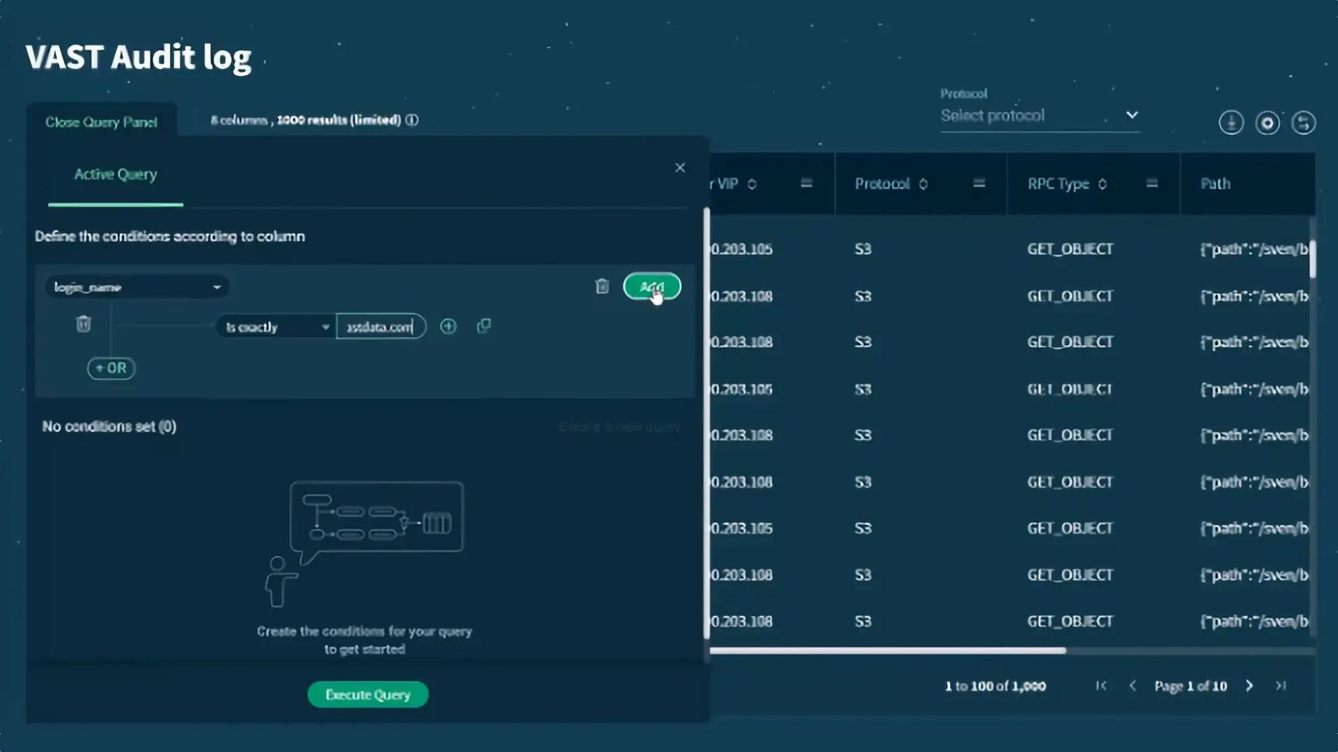
Accessing the Audit Table Through The VAST GUI
Even better, since the audit table is just another VAST database table, customers can slice and dice their audit data with standard SQL tools like Apache Superset, as shown in the examples below. The JSON files only contain data for fields that make sense for the I/Os, and each entry describes the audit table as having a column for every attribute tracked for access via any protocol. The contents of incongruous columns, like S3_Bucket_Name for an SMB read are null.
Using the Audit Table for Usage and Performance Management
The VAST audit table has one other big advantage over the JSON version, and most other systems’ similar logs are designed to address forensic security analysis. The audit table includes two columns with additional data: the number of requests consolidated into each row and the byte total for those requests.
That additional information means the audit table isn’t just the source of truth for forensic security but also a source of insight into how the system is being used and the demands workloads make on the system. Since that data is in a SQL table database visualization tookits like Apache Superset make it easy to create reports for the top users and busiest files or activity dashboards as shown below.
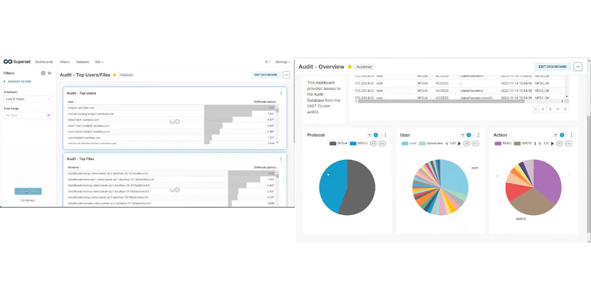
Visualizations from the Audit Table Using Apache Superset
The Audit Table is a companion to The VAST Catalog, where the Catalog provides a view into what a system was holding at any point in time; the Audit Table provides a view into what the system was doing. Together, they can provide powerful insights.
Finally, the Audit Table can be used to characterize workloads and applications. Each audit entry describes a set of reads or writes, providing the number of I/Os and total bytes with a timestamped entry every few seconds. This makes it easy to calculate:
The average size of reads and write I/Os
The I/O rate (in IOPS) for reads and writes
The ratio of reads to writes
Once you’ve done this for the pilot application, you can produce a workload definition for a benchmark like FIO or ElBencho that produces the same I/O pattern as the application so you can stress test your infrastructure before putting the pilot in production where it will perform 1000 times the I/O the pilot did.
Gemini
The VAST Business Model
Before VAST customers bought storage under one of two models:
The appliance model – Most enterprise storage is sold under the appliance model where vendors sell, and/or customers buy depending on your point of view, storage appliances. Each appliance includes hardware, and an OEM license for the vendor’s software to run on that hardware. Under the appliance model there’s a large initial cost for hardware and software and a smaller annual support and maintenance cost.
Software-Defined Storage (SDS) – Under the SDS model customers buy storage software and compatible hardware, typically industry standard x86 servers and drives separately or through an integrator.
Under the appliance model customers have just one vendor to call for support, when a component fails, or a system is misbehaving they open a ticket support and get the problem solved and the component replaced. Most vendors engineer their systems so SSDs won’t wear out during the system’s working life, but a few exclude coverage for worn SSDs from their support agreements.
Vendors take advantage of customers under the appliance model in two ways. First by forcing customers to buy new software licenses when they upgrade/update their hardware and second by boosting support costs on renewals to make the cost of an upgrade to new hardware, and therefore a relicense of the software more attractive.
Many customers reacted to the appliance model by moving to software defined storage. This allowed those customers to avoid huge markup enterprise vendors added to the cost of x86 servers and disk drives, but it left customers, or their integrators on the hook for designing and maintaining their systems.
Gemini Disaggregates Hardware from software
The appliance model forces customers to purchase storage hardware and OEM licenses to the vendor’s storage software for the full capacity of that hardware together in a single transaction. Just as DASE disaggregates the computing power of a systems from the storage capacity, VAST’s Gemini model disaggregates the hardware and software purchases.
Under Gemini customers purchase a Gemini subscription, from VAST, that combines a license to run the VAST software and support/maintenance for both the software and the Gemini Supported hardware it runs on. VAST provides first and only touch support for both the hardware and the software. When an SSD, or a fan fails in a VAST cluster the system sends an alert as part of its analytics stream to VAST Support and a support engineer contacts the customer to arrange replacement.
VAST customers get that Gemini Supported hardware through one of VAST’s worldwide manufacturing partners. VAST has arranged for these manufacturing partners to provide Gemini Supported hardware to VAST resellers at VAST’s negotiated cost that takes advantage of the combined volume of all VAST’s customers.
This combination means that VAST customers, like the roll-your-own SDS crowd, avoid the huge markups enterprise storage vendors have on commodity components like SSDs without giving up on the stability, and security of running a system where one vendor, VAST, is responsible for supporting the whole shooting match.
Priced By Useable Capacity
Regardless of whether they sold appliances with OEM licenses or software that turns servers and SSDs into software defines storage storage vendors with capacity based pricing have traditionally made users license the total raw capacity of their hardware. To run vendor W’s file system on your cluster of 4 nodes each with 150 TB of SSDs you’d have to purchase a 600 TB license.
Gemini agreements by comparison are priced not by the raw capacity of the hardware but by the useable capacity the customer plans to consume, in 100 TB increments. If a VAST customer only plans to put 200 TB of data on their cluster that has 338 TB of raw hyperscale flash they can buy a 200 TB Gemini subscription. If their data grows faster than expected they can purchase an additional 300 TB subscription, and if they ask nice their sales exec will make the new agreement co-terminus with the existing 200 TB subscription.
Note that licenses are for useable capacity, that is the space after erasure coding but before data reduction so the additional capacity created by data reduction is entirely to the customer’s benefit. A customer with a 200 TB Gemini agreement could store 376 TB of data that reduces 2:1 and still be will within their licensed capacity.
Infinite Cluster Lifetime
As we’ve already seen the VAST DASE architecture allows VAST customers to scale their system both asymmetrically and heterogeneously. A single VAST cluster can include VAST Servers (CNodes) of different generations with different amounts of compute power and VAST Enclosures (DBoxes) of different capacities over multiple generations in a storage pool and namespace.
Gemini’s disaggregation of hardware and software means that unlike the OEM licenses enterprise vendors have traditionally used Gemini subscriptions are transferrable. If a customer replaces old DBoxes with new denser DBoxes they can simply transfer the Gemini Agreement to the new Dbox(es). They’ll probably need to add licenses because they’ve added capacity but VAST customers don’t have to include the cost of a software upgrade in their calculations of the cost of a hardware refresh.
Customers can replace appliances, when the density, performance and power consumption advantages of new appliances dictate and transfer any remaining subscription time to the new appliances. Since customers buy hardware directly from VAST’s manufacturing partner at cost there’s no pressure for VAST to encourage replacement hardware purchases and the software re-buys that go with them.
A VAST cluster is immortal for as long as a user wants. New Servers and Enclosures are added to clusters as performance and/or capacity is needed, and older models are aged out as their utility diminishes. While the hardware evolves over time, the cluster lives through a progressive number of expansion and decommission events without ever requiring users to forklift upgrade anything, ever.
Eliminate Forced Upgrades With 10-year fixed rate Gemini
The last step in improving the economics of an all-flash storage system is extending its lifecycle, Storage systems have historically been designed for a 3–5-year lifecycle, storage vendors enforce this by inflating the cost of support in later years – making it more economical to replace a storage system than renew its support contract. These same vendors then get drunk on the refresh cycle sale and their investors are conditioned on the 3–5-year revenue cycle that comes from this refresh selling motion.
Gemini Supported appliances are designed for a 10-year deployment life. As long as an appliance is covered by a Gemini subscription VAST will provide hardware support and failed component replacement for up to 10 years from the appliance’s initial installation. While Gemini subscription prices will be reset periodically for competitive reasons VAST customers will never be charged more for their subscription over time.
Hyperscale flash and 10-Year Endurance
One of the primary design tenets of the VAST DataStore is to minimize the write amplification caused by normal namespace churn. The VAST DataStore writes and manages data on SSDs in patterns that cause less than 1/20th the flash wear of random writes. The VAST Datastore wear levels across SSDs in the cluster and acts as a global flash translation layer extending flash management from being strictly an SSD function to managing a global pool of flash.
The result of this combination of inventions is a Cluster architecture that requires 1/10th of the endurance that can be realized from today’s generation of commodity SSDs. While this super-naturally high level of system-level endurance paves the way for VAST’s future use of even denser flash media, such as PLC flash, it also enables customers to rethink the longevity of data center infrastructure. The net result is that since SSDs don’t have the moving parts that cause HDD failure rates to climb after 5 years of use, and VAST’s global flash management limits flash wear VAST systems can run in user data centers for 10 years. VAST will replace any failed component, including SSDs that have exhausted their flash endurance, on any system under a Gemini subscription and will offer Gemini subscriptions for up to 10 years from appliance installation.